Dynamically reconfigurable directionality of plasmon-based single photon sources Yuntian Chen,1, 2 Peter Lodahl,1 and A. Femius Koenderink2, ∗
arXiv:1007.1618v1 [physics.optics] 9 Jul 2010
1 DTU Fotonik, Department of Photonics Engineering, Ørsteds Plads, Building 343, DK- 2800 Kgs. Lyngby, Denmark. 2 Center for Nanophotonics, FOM Institute for Atomic and Molecular Physics (AMOLF), Science Park 104, 1098 XG Amsterdam, The Netherlands (Dated: July 12, 2010)
We propose a plasmon-based reconfigurable antenna to controllably distribute emission from single quantum emitters in spatially separated channels. Our calculations show that crossed particle arrays can split the stream of photons from a single emitter into multiple narrow beams. We predict that beams can be switched on and off by switching host refractive index. The design method is based on engineering the dispersion relations of plasmon chains and is generally applicable to traveling wave antennas. Controllable photon delivery has potential applications in classical and quantum communication. PACS numbers: 73.20.Mf, 07.60.Rd, 78.67.Bf, 84.40.Ba
Controllably and efficiently extracting photons from single quantum emitters into a well-defined set of modes is a holy grail for quantum optics, optical quantum computation, as well as single molecule spectroscopy. The conventional approach is to place the emitter inside a high finesse ultrasmall cavity, such as a micropillar1,2 , microsphere or toroid3 , or photonic crystal cavity4 . Alternatively, several groups have started to pursue plasmonic systems for quantum optics.5 By virtue of the large interaction strength of free electrons in noble metals with photons at optical frequencies, plasmon polaritons offer very tight field confinement over large frequency bandwidths. In addition to applications in subwavelength optoelectronics and near-field sensors,6 plasmonics hence offers rich perspectives for quantum optics with single plasmons5 , and for novel broadband single-photon sources based on plasmon antennas. For instance, several researchers recently proposed that broadband highly directional single-photon sources can be made using plasmon particle array antennas that mimic directional radio frequency antennas.7,8 We also note that ultrafast plasmonic phenomena and all-optical plasmon modulators were studied recently.9 In a quantum network in which several localized qubits interact via emission of photons, one would desire reconfigurable coupling between nodes in the network of qubits. By analogy to radio-wave antennas, one might expect that plasmon antennas used to control emitters can be reprogrammed with ease to arbitrarily steer beams. However, programmable radio-wave antennas use methods inaccessible to plasmonics, as they usually use individual phase control over many active elements. In this paper we propose a new strategy to obtain control of reconfigurable plasmon antennas for single emitters. Our method rests on controlling the dispersion relation of guided modes in each part of a multi-arm traveling wave plasmon antenna by switching the refractive index of the surrounding medium. Intuitively, the large bandwidth of plasmonic antennas implies that larger index changes are needed to switch than in high Q dielectric cavities. We show that an effective reconfigurable switch can be reached with host index changes that are achievable with liquid crystals.10 We consider multi-beam antennas that split the stream of photons emitted by a single emitter into several channels, as
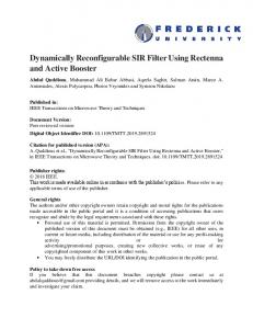
FIG. 1: Sketch of our reconfigurable nano-antenna concept to control single emitters. We consider a single emitter (red dipole) embedded in a set of linear plasmon antennas (metal particles in yellow) that intersect at the emitter. In its unswitched state (left), such an antenna funnels spontaneous emission into different beams. The beams can be switched on and off (indicated by “ZAP”) at will by modifying the particle or host material dynamically.
shown in Fig. 1, each corresponding to a narrow beam of < 30 degree full width at half maximum.7,8 We explore the possibility of dynamically switching on and off each beam at will, for instance by controlling the refractive index surrounding the antenna. We envisage that such a dynamically reconfigurable multi-beam antenna can be useful in quantum optics, to controllably couple a local qubit to a select number of other qubits. First, let us consider how the multi-beam antenna works in its unswitched state. Following a proposal by Li et al.11 , we propose that a multi-beam antenna with N beams can be made by combining N antenna arms that each consist of a linear array of metal particles, and essentially act like Yagi-Uda type antennas at optical frequencies. Recent reports have shown that such antennas can force single emitters to emit into a narrow beam over a broad bandwidth that is demarcated on the blue edge by an abrupt cut-off. The cut-off wavelength depends on antenna geometry8. The physics can be understood by considering a Yagi-Uda antenna as a traveling wave antenna, the behavior of which is governed by the dispersion relation for an one dimensional infinite plasmon chain.12 When the emission frequency is tuned to the lower dispersion branch, the emitter decays into a plasmonic mode bound to the antenna, and with a wave vector beyond the light line, see Fig. 2-(b). The finite antenna length causes efficient
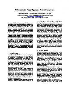
2 out-coupling of this mode, which hardly radiates in the case of infinite plasmon chains. For a linear plasmon particle array of length L, momentum conservation is only defined within △k ≈ π/L. This determines the cut-off wavelength of efficient beaming. The wavelength at which the dispersion relation deviates more than △k from the light line, marked by the blue bar in Fig. 2-(b), corresponds to the cut-off wavelength. If the operation wavelength denoted by λop , is longer than the cut-off wavelength, the plasmon chain acts as a directional antenna for single-photon emission. If λop is shorter than the cut-off wavelength, the emitter decays into dark plasmons.8 Importantly, the cut-off is very sharp and occurs within a few nanometer spectral bandwidth.8 Such abrupt on/off behavior is essential for optical switching of plasmon antennas. As a first example, we study the coupling of a single emitter to an antenna with two identical arms, consisting of silver spheres17 (radius R = 55 nm) , arranged in a linear array with pitch of d = 160 nm, shown in Fig. 2-(a). The array is embedded in glass (n = 1.5) and the dipole emitter is transverse to the arrays. The real part of the corresponding infinite chain dispersion relation for the transverse mode, (black curve in Fig. 2-(b)), is calculated from a point-dipole model.12 Since both arms are identical, they have exactly the same dispersion relation, and the emitted photon is split into two identical beams. As in the case of a single Yagi-Uda antenna, the beams have a full width at half maximum of 30 degrees, as calculated using “MESME”. “MESME” is an exact electrodynamic multiple scattering multipole expansion method developed by F. J. Garc´ıa de Abajo for rigorously solving Maxwell’s equations for finite clusters of scatters.8,13 The fact that we choose a linear antenna (1800 between arms) is not essential: we obtain similar splitting into two beams for perpendicular arms. We consider how much perturbation is required to switch one of the two beams off. Two facts are immediately obvious: First, since we start with a symmetric antenna, we require an asymmetric perturbation to switch only one of the beams. Second, we expect a dramatic change in emission pattern only if the perturbation shifts the cut-off wavelengths through λop . Therefore λop is chosen close to the cut-off wavelength. Before focusing on a specific switching mechanism, we note that the key parameter that determines the dispersion is the polarizability α of each particle. In the electrostatic approximation we have α = 3V (ε − n2 )/(ε + 2n2 ), with particle volume V = 4πR3 /3, host index n and metal dielectric constant ε. To obtain a first estimate for the amount △α needed to shift the dispersion sufficiently, we vary △α through △R, even though this may not be physically realizable in a dynamical manner. We discuss realistic implementations below. We find that at fixed pitch and host index, the dispersion red shifts as particle size increases, c.f the red curve in Fig. 2 (b). When the particle size is increased from R = 55 nm to R = 58 nm, the shift amounts to ∼ 20 nm, which moves the cut-off wavelength through λop . We therefore expect a dramatic change in radiation pattern. Indeed the calculation (Fig. 2-(c-d)) shows that a single beam remains from the unswitched arm, and disappearance of the beam from the switched arm. In order to quantify the quality of the switching behavior, we define two figures of merit. The first figure of merit
FIG. 2: (a) Sketch of the emitter-antenna geometry consisting of two identical arms. We consider a single emitter placed in the middle of a 160 nm gap between the antenna arms, oriented perpendicular to the antenna axis. (b) The black (red) curve represents the dispersion relation for the transverse plasmon modes of an infinite Ag particle chain in glass (pitch d=160 nm, particle size R=55 (58) nm). The black horizontal line indicates the operation wavelength at 652 nm. (c/d) Emission pattern at λ = 652 nm for a single emitter embedded in a linear array antenna, with 8 silver particles to each side. In (c) both arms are equal (R=55 nm). In (d) the right arm has R=58 nm. (e) Radius/host index (top axis) dependence of the beaming fraction and beam contrast, assuming collection in a cone of width sin θ = 0.32.
called the beaming fraction F , quantifies how much of the total emitted power is emitted R into the leftR arm and right arm, respectively Fleft/right = (Ω ,left/right) P dΩ/ (4π) P dΩ, where P 0 is the power radiated per solid angle. We define a solid angle Ω0 , which we take to correspond to a numerical aperture NA = sin(θ), that one would use to collect the radiation of each beam in practice. The second figure of merit called the beam contrast B = Fleft /Fright quantifies the on/off contrast, and is defined as the brightness contrast between the two arms. We plot both figures of merit in Fig. 2-(e) for different magnitudes of the perturbation of the right hand arm of the antenna.
λ (nm)
λ (nm)
3
680
F right
650
0.4
620
0.3
680
0.2
F left
0.1 0
650 620 1.4
1.45 1.5 1.55 Index of host material
1.6
FIG. 4: Contour plot of beaming fraction F versus host index and wavelength. The dashed white lines denote the cut-off wavelengths for the directional emissions. In a 30 nm band to the red of the cutoff of the right arms, both beams have comparable power. In between the cutoffs, the right beam is off, and the left beam is brighter.
FIG. 3: Results for an asymmetric two beam antenna, with radius R = 50 nm, pitch d = 140 nm (left arm) and R = 55 nm, d = 160 nm in the right arm. (a/b) shows the dispersion relation for transverse plasmons for each arm before (black curve) and after the switch (red curve). (c/d) Emission pattern for a single emitter in the antenna (both arms with 8 particles) before (c) and after (d) switching host index from 1.5 to 1.56. (e) Host index dependence of the beaming fraction and beam contrast at λ = 662 nm. (f) Quantum efficiency versus the variation of host index at λ = 662 nm.
At R = 55 nm, both arms are equal and carry equal amounts of energy (B = 1). For a fixed NA = 0.32 one would collect a fraction of ∼ 20% of emitted power in each beam. For particle size R=58 nm in the right hand beam, the right beam is strongly reduced to below ∼ 3%. At the same time the left beam gains a factor two in brightness. The contrast between the beams hence shifts from B = 1 to several hundred. In order to translate the required △R back to a physically realizable switch, we note that ∆R/R ∼ 10%. We hence conclude that a two-beam antenna with identical arms can be reconfigured provided one finds a way to change the polarizability of particles in one arm of the antenna by 30%. Since the only feasible method to change polarizability is to change the host index, we convert △α into a required change in host index
(top axis in Fig. 2 (e)). An immense change from n = 1.5 to n = 1.85 would be required, which is unachievable in any practical material. We conclude that prospects for switching are dim when one starts out from antennas that are symmetric. To overcome these challenges, we now consider a twobeam antenna that consists of different arms to begin with. Due to the asymmetric geometry in which particle size and pitch are chosen smaller (R = 50 nm, d = 140 nm) in the left arm already at the fabrication stage, the dispersion relation for the two arms are shifted already in the unswitched case, shown in Fig. 3 (a). In the right hand branch, λop is much closer to the cut-off than in the left branch. This yields the possibility of switching just one beam off selectively by a homogenous switch in host material index, provided that the cut-off of the right hand branch shifts beyond λop , while λop remains to the red side of the cut-off in the left arm. Figure 3 (c) shows that in the unswitched (n = 1.5) state, the emission from the emitter is indeed split into two beams. Due to the intrinsic asymmetry in geometry, both beams do not have equal angular width, although they carry comparable power. As the host index is raised from 1.5 to 1.56, the dispersion curves bend further away from the light line, shifting the cut-off wavelength in both branches to the red (Fig. 3 (b)). Figure 3 (d) confirms that the left beam remains, while the right beam switches off, in accordance with the shift in cut-off wavelengths. Figure 3 (e) allows us to assess the figures of merit of the proposed switch, assuming λop = 662 nm. We plot the dependence of the beaming fraction, and the beam contrast as a function of host index. While the beam contrast is approximately equal at n = 1.5, we see a marked contrast between left and right beams at n > 1.56. Hence we conclude that beams in a multi-beam antenna can be switched at will with a manageable index change, provided we carefully choose the dispersion relation for each antenna branch. The role of the dispersion relation is further confirmed in Fig. 4, which shows the beaming fraction for the two arms as a function of both operation wavelength and host index. There is a band throughout which each arm shows pronounced directional emission with
4 approximately equal power. To the blue side of the cut-off of the right hand arm, the right hand beam has very low intensity, and the intensity of the left arm is increased by a factor of 2. To the blue of the cut-offs of both waveguides, neither arm generates a bright and directional beam. This result shows that the switch can be optimized for any λop in a wide band, by antenna geometry and host index, and that due to the sharp antenna cut-off only modest index changes are required, which are achievable in practice. We believe that the design philosophy presented here is generally valid in any traveling wave antenna system in which the dispersion relation imposes a sharp and tunable cut-off for each antenna arm. The figures of merit can hence be expected to improve as new traveling wave antenna designs are proposed in the field of plasmonics. In closing, we have proposed a method to realize reconfigurable plasmon antennas, e.g., for controlling the coupling of single emitters with nodes in a quantum network. Essential for our method is the dispersion relation underlying traveling wave antennas that provides a sharp tuneable cut-off. The specific design for a two beam antenna presented in this paper uses host refractive index changes from n = 1.5 to n = 1.56. Such changes are in the range accessible with liquid crystals and phase change materials,10,14 but above the level accessible with, e.g., photochromic polymers15 or thermal index tuning. Particularly promising is the use of a photo sensitive liquid crystal with potentially picosecond response time to UV pulses.10,15 Embedding the Yagi-Uda antennas inside a semiconductor matrix (Si or GaAs) would allow fast and reversible switching using free carrier excitation.16 The operation wavelength in that case shifts to the infrared due to the high host index. In addition to the specific refractive index demands,
∗ 1
2
3
4
5
6
7
Electronic address:
[email protected] J. M. G´erard, B. Sermage, B. Gayral, B. Legrand, E. Costard, and V. Thierry-Mieg, Phys. Rev. Lett. 81, 1110 (1998). M. Pelton, C. Santori, J. Vu˘ckovi´c, B. Zhang, G. S. Solomon, J. Plant, and Y. Yamamoto, Phys. Rev. Lett. 89, 233602 (2002). D. Armani, T. Kippenberg, S. Spillane, and K. Vahala, Nature 421, 925 (2003). T. Yoshie, A. Scherer, J. Hendrickson, G. Khitrova, H. M. Gibbs, G. Rupper, C. Ell, O. B. Shchekin, and D. G. Deppe, Nature 432, 200 (2004). D. E. Chang, A. S. Sørensen, P. R. Hemmer, and M. D. Lukin, Phys. Rev. Lett. 97, 053002 (2006); A. V. Akimov, A. Mukherjee, C. L. Yu, D. E. Chang, A. S. Zibrov, P. R. Hemmer, H. Park, and M. D. Lukin, Nature 450, 402 (2007); Y. C. Jun, R. D. Kekapture, J. S. White, and M. L. Brongersma, Phys. Rev. B 78, 153111 (2008); Y. Chen, T. R. Nielsen, N. Gregersen, P. Lodahl, and J. Mørk, Phys. Rev. B 81, 125431 (2010). I. I. Smolyaninov, J. Elliott, A. V. Zayats, and C. C. Davis, Phys. Rev. Lett. 94, 057401 (2005); J. Takahara, S. Yamagishi, H. Taki, A. Morimoto, and T. Kobayashi, Opt. Lett. 22, 475 (1997); S. I. Bozhevolnyi, V. S. Volkov, E. Devaux, J.-Y. Laluet, and T. W. Ebbesen, Nature 440, 508 (2006). H. F. Hofmann, T. Kosako, and Y. Kadoya, New. J. Phys. 9, 217 (2007); J. Li, A. Salandrino, and N. Engheta, Phys. Rev. B 76, 245403 (2007); T. H. Taminiau, F. D. Stefani, and N. F. van Hulst,
we note several obstacles for reconfigurable optical antennas. First we note that despite the high directivity evident in Figs 2 and 3, the side lobes contain a significant fraction of the far field emission. Indeed, at an NA of 0.32 considered here, the two beams contain only about 50% of the emitted power (Fig. 3(e)). Enlarging the NA, or embedding the nanoscale antennas in micron scale dielectric waveguides will suppress the side lobes, while retaining high light matter interaction strength. As a second obstacle, we note that turning off a beam does not necessarily double the brightness of the remaining beam, as is evident from the drop in quantum efficiency in Fig. 3(f). The quantum efficiency is reduced because the branch that is switched off still captures emission in the form of dark plasmons. Such losses can be avoided by using other resonant scatterers. We have calculated that Yagi-Uda antennas also work when made from high index (Si) particles. This configuration not only avoids loss but would also allow easier switching, since the particles themselves can be optically switched. Thirdly we notice that Yagi-Uda antennas are limited by the fact that the dispersion cut-off only occurs at one edge (blue edge). In multi-beam antennas with more than 2 beams it is hence not possible to switch arbitrary combinations of beams. Nonetheless, our design strategy paves the way for designing single emitter networks for quantum optics on the chip. We are especially indebted to Javier Garc´ıa de Abajo for providing MESME code. We also gratefully acknowledge support from Villum Fonden. This work is part of the research program of the “Stichting voor Fundamenteel Onderzoek der Materie (FOM),” which is financially supported by the “Nederlandse Organisatie voor Wetenschappelijk Onderzoek (NWO).” AFK thanks NWO-Vidi and STW/Nanoned.
8 9
10
11
12 13
14
15
16
17
Opt. Expr 16, 10858 (2009); T. Kosako, Y. Kadoya, and H. F. Hofmann, Nature Phot. 4, 312 (2010). A. F. Koenderink, Nano Lett. 9, 4228 (2009). K. F. Macdonald, Z. L. Samson, M. I. Stockman, and N. I. Zheludev, Nature Phot. 3, 55 (2008); D. Pacifici, H. J. Lezec, and H. A. Atwater, Nature Phot. 1, 402 (2007); R. A. Pala, K. T. Shimizu, N. A. Melosh, and M. L. Brongersma, Nano Lett. 8, 1506 (2008). P. El-Kallassi, R. Ferrini, L. Zuppiroli, N. L. Thomas, R. Houdr´e, A. Berrier, S. Anand, and A. Talneau, J. Opt. Soc. Am. B 24, 2165 (2007). J. Li, A. Salandrino, and N. Engheta, Phys. Rev. B 79, 195104 (2009). A. F. Koenderink and A. Polman, Phys. Rev. B 74, 033402 (2006). F. J. Garc´ıa de Abajo and A. Howie, Phys. Rev. Lett. 80, 5180 (1998); F. J. Garc´ıa de Abajo, Phys. Rev. B 60, 6086 (1999). C. Arnold, Y. Zhang, and J. G. Rivas, Appl. Phys. Lett. 96, 113108 (2010). K. G. Yager and C. J. Barrett, J. Photochem. Photobio. A, 182, 250 (2006). T. G. Euser, A. J. Molenaar, J. G. Fleming, B. Gralak, A. Polman, and W. L. Vos, Phys. Rev. B 77, 115214 (2008). We use tabulated constants from E. D. Palik, Handbook of optical constants of solids II (Academic Press, 1991).