calls the rc_control to enable the new module as if the downloaded bitstream were written to the configuration ... as towards the IOs of the RM, and are kept until the .... Exploration of Reconfigurable MPSoCs,â in Conference on Adaptive.
IEEE International Symposium on Field-Programmable Custom Computing Machines
Modeling Dynamically Reconfigurable Systems for Simulation-based Functional Verification Lingkan Gong and Oliver Diessel School of Computer Science and Engineering University of New South Wales {lingkang,odiessel}@cse.unsw.edu.au These problems suggest that new methods and tools need to be provided to assist designers with the functional verification of DRS.
Abstract—Dynamically Reconfigurable Systems (DRS), which allow logic to be partially reconfigured during run-time, are promising candidates for embedded and high-performance systems. However, their architectural flexibility introduces a new dimension to the functional verification problem. Dynamic reconfiguration requires the designer to consider new issues such as synchronizing, isolating and initializing reconfigurable modules. Furthermore, by exposing the FPGA architecture to the application specification, it has made functional verification dependent on the physical implementation. This paper studies simulation as the most fundamental approach to the functional verification of DRS. The main contribution of this paper is in proposing a verification-driven top-down modeling methodology that guides designers in refining their reconfigurable system design from the behavioral level to the register transfer level. We assess the feasibility of our methodology via a case study involving the design of a generic partial reconfiguration platform.
While design errors in reconfigurable systems do not require re-fabricating chips, functional verification is an important, time-consuming and costly step in the design process. Accelerating verification closure can reduce time-to-market and thus considerably reduce the cost and enhance the profitability of a DRS design project. Moreover, releasing undetected bugs in a design may incur significant recovery costs, and, for critical applications such as aviation, finance and defense, may be impossible to recover from. Given the difficulty and the importance of verifying the functional correctness of DRS, this paper focuses on the modeling methodology, which is a crucial determinant in facilitating simulation-based functional verification for such systems. Borrowing a widely accepted concept from the ASIC community, this paper proposes a top-down modeling methodology that guides designers in refining their reconfigurable design from the relatively abstract behavioral modeling level to the implementation-ready, Register Transfer Level (RTL) for the purpose of functional verification. The key contributions are
I. I NTRODUCTION Dynamically Reconfigurable Systems (DRS) can be partially reconfigured at run-time without affecting the execution of the remaining logic. Such additional flexibility over traditional static hardware systems enables DRS to adapt to changing execution requirements while at the same time improving performance and power consumption [1]. However, such flexibility has also resulted in significant challenges in ensuring the functional correctness of the DRS.
•
The ability to reconfigure DRS on-the-fly has added a new dimension to the functional verification problem. First of all, designers have to consider the new features that do not exist in purely static designs, such as how to synchronize the reconfiguration so that no data is lost when swapping reconfigurable modules (RM) in and out; how to isolate the RM undergoing reconfiguration to avoid providing unexpected data values to the static part; and how to initialize the newly downloaded RM before commencing execution. Moreover, as dynamic reconfiguration has made the behavior of the system dependent on the physical reconfigurable fabric, including the configuration memory and the bitstreams [2], accurate functional verification can only be performed after the timeconsuming physical implementation step. This conflicts with the general hardware design principle, which requires functional verification to be performed as early as possible because fixing a bug involves an iteration of the design cycle and the later the bug is found the higher the cost it may incur. 978-0-7695-4301-7/11 $26.00 © 2011 IEEE DOI 10.1109/FCCM.2011.18
•
•
Describing the potential bugs introduced by the new features of dynamic reconfiguration at all stages of the reconfiguration process. Extending the top-down modeling methodology already proven successful in the ASIC community, so as to detect the potential bugs identified in DRS. A case study on the modeling of DRS at different levels of abstraction, so as to provide a concrete example of how to use the top-down methodology to cover some typical bugs.
In this paper, the DRS considered are restricted to using coarse-grained or modular reconfiguration that is performed by loading new configuration bitstreams. We only consider the cycle-accurate behavior of DRS and ignore physical implementation errors such as glitches and timing violations. The listing and analysis of potential bugs we provide is at an early stage; we have almost certainly not covered them all. Nevertheless, we hope to inspire other researchers and designers to consider the value of simulation and to adopt 9
modified SystemC kernel is not standard and is incompatible with existing design flows.
a systematic top-down modeling methodology to facilitate functional verification instead of performing ad-hoc testing or moving on to the implementation stage without achieving functional verification closure. Unfortunately, we have not been able to automatically eliminate the set of bugs we have so far identified. Like similar approaches in the ASIC community, our modeling methodology therefore only serves as a guide for researchers and designers who need to create their own specific simulation environment, and in so doing, helps manage the verification process.
Some other examples using SystemC as a modeling language can be found in [10], [11], [12]. These works focus on design space exploration, the primary concern of which is to partition the design into static and dynamic parts and hide the reconfiguration details. In terms of verification, they do not capture enough low-level information to assist with debugging the reconfigurable features. The Dynamic Circuit Switch (DCS) [2], [13] is a systematic study of modeling the DRS at RTL level. The idea is to add simulation-only artifacts to the VHDL description of the hardware. The artifacts include, for example, Task State Registers, Dynamic Task Selectors and so on. However, the VHDL artifacts can not be reused, and can only model the DRS at RTL level.
The rest of this paper is organized as follows. Section 2 provides an overview of related efforts to model DRS. In Section 3, we summarize the bugs that may be present in the design and affect the reconfiguration process. We define the requirements of an ideal modeling methodology based on our analysis. Section 4 discusses the proposed top-down modeling methodology. Section 5 illustrates the use of our methodology in the design of a generic reconfigurable computing platform and Section 6 concludes the paper.
Table I summarizes the current research. It can be seen that while much effort has been invested in modeling dynamic reconfiguration, there has only been limited study of how to facilitate the functional verification of DRS. For example, all existing methods assume a compile-time defined delay for deactivating/activating an RM. As a result, they fail to accurately simulate systems that share the application datapath with the bitstream datapath, and thus cannot assist in assessing the impact these two streams may have on each other. Additionally, previous efforts have lacked a clearly defined boundary between behavioral level modeling and Transaction Level Modeling (TLM) despite their different objectives. While a TLM model should define the system architecture and component interactions, behavioral modeling does not require such distinctions to be made.
II. R ELATED W ORK Current research on the modeling of dynamic reconfiguration focuses on creating customized languages and extending existing languages. Although customized languages such as JHDL [3] and Lava [4] are more flexible, they are difficult to integrate into existing design flows and have therefore had little impact on industry. On the other hand, because existing languages such as VHDL/Verilog and SystemC [5] do not support changing the logic at run-time, much current work is directed at extending existing languages to model dynamic reconfiguration. ReChannel [6], [7] is a SystemC-based, open source library to model dynamic reconfiguration. In ReChannel, RMs are derived from the rc_reconfigurable base class and are connected to the static design through an rc_portal, a MUX-like SystemC class. The built-in class rc_control provides reconfiguration control such as unloading and activating an RM. The original work only focuses on high-level modeling. In this work, we extend this library to support behavioral modeling down to RTL level.
III. C HALLENGES IN V ERIFYING DRS Dynamic reconfiguration imposes new challenges on the functional verification of a system. From a temporal perspective, these challenges can be categorized according to the state of progress of the reconfiguration process, i.e. BEFORE, DURING, and AFTER reconfiguration. Table II summarizes the potential bugs we have identified at each of these stages of reconfiguration. The table is, no doubt, incomplete, and therefore only provides examples which illustrate the difficulties of verifying DRS. We describe each of the potential bugs we have identified so far in more detail below.
OSSS+R [8] is a design methodology for automatic modeling, synthesis, and simulation of DRS. The underlying philosophy is to treat dynamic reconfiguration separately from a system’s functional specification; the tool can then automatically generate the necessary reconfiguration controls. However, such automatic synthesis methodologies do not support the functional verification of manually specified, customized DRS designs.
BEFORE reconfiguration: The time interval from when a request for reconfiguration is generated until just before the first byte of the bitstream is written to the reconfiguration port of the FPGA. During this stage, the static part should synchronize with the RM so as to ensure no data is lost [6]. Generally speaking, the designer has three options to perform the synchronization.
Brito et al [9] attempt to model DRS by modifying the SystemC kernel. The authors add to the SystemC kernel a configlist, which keeps track of the state of all RMs and stops executing a thread if the corresponding RM is deactivated. A significant drawback of this work is that the
Firstly, for a pipelined RM in a streaming application, the data can be flushed without synchronizing, and the RM can
10
Table I C OMPARING DRS MODELING LANGUAGES
Concepts
Modeling Method
Comments
ReChannel [6], [7]
A SystemC based library that provides flexible macros, classes, functions to model dynamic reconfiguration
- Interleaves communication via a MUX-like rc_portal - Extend standard sc_module with sync. & reset properties - Use rc_control to control reconfiguration (e.g., unload, activate)
- Can build the simulation environment on top of the library - Does not cover the RTL details
DCS [13]
[2],
Adding simulation artifacts to the VHDL description
- Interleaves communication via an HDL MUX - Use simulation only artifacts to sync. & isolate
- Captures the RTL details - Have to build the simulation environment from scratch
Modifying the SystemC kernel [9]
Modifying the SystemC simulation kernel to support time-variant hierachy
- Disable the SystemC thread when deactivated
- Non-standard SystemC kernel can not be integrated with existing design flows
OSSS+R [8]
Automatic modeling, synthesis, and simulation of DRS
- Use SystemC polymorphic classes - Synthesize the controller automatically
- Seperates dynamic reconfiguration from the functional specification of the design - Fails to support customized reconfiguration controllers
Table II P OTENTIAL BUGS BEFORE, DURING, AND AFTER RECONFIGURATION
BEFORE Recon.
DURING Recon.
AFTER Recon.
Concept
Request to reconfigure the RM → Just before the first byte of the bitstream is written
Writing configuration bitstream
Just after the last byte of the bitstream is written → RM activated
Design considerations
- Synchronization of the old RM - Unloading the old RM
- Isolation - The bitstream datapath
- Initialization of the new RM - Activating the new RM
Potential bugs
- Recording the flushed data - Circular waiting & deadlock - Draining the pipelines - Multiple reconfig. requests - Inconsistent state of the RM - Implementation dependent logic to save states
- Unpredictable effects of the static part - Timing of isolation - Waiting for non-exsiting feedback - Shared datapath between the bitstream and the application
- Previous RM not cleared - Timing of the reset signal - Initialization of pipelined designs
Bug # 4. The static part keeps sending data to the RM after the RM has acknowledged the reconfiguration, and places the RM into an in-consistent state. Bug # 5. If the system saves state by reading back the configuration memory, bugs in the read-back logic cannot be verified without knowledge of physical implementation details such as the frame addresses of the RM. This represents an undesirable level of detail for functional verification purposes.
refill the pipeline with the flushed data when and if it is again swapped in later. In this approach, Bug # 1. Failing to record the flushed data correctly can cause the RM to later restart with incorrect data.. The second option is to wait for the RM to finish. In this case, the RM should not acknowledge the reconfiguration request until it has processed all the data. However,
DURING reconfiguration: The period during which the configuration bitstream is being written to the reconfiguration port of the FPGA. During this stage, the behavior of the logic inside the reconfigurable region is undefined and may introduce potential bugs into the system. For example,
Bug # 2. For complex RMs having multiple FSMs or pipelines, extra care should be taken to wait for all FSMs to enter the idle state and/or to drain all pipelines of data. This may result in circular waiting and deadlock. Bug # 3. An RM may receive multiple reconfiguration requests that conflict with each other, such as to unload an already unloaded module [14] or to cancel an acknowledged request.
Bug # 6. The default value of the newly downloaded bitstream may drive erroneous signals onto the static side. Even if such default value won’t cause errors on the static side, there is no guarantee that during the reconfiguration process signals are held at their default values.
The third option is to save the state of the RM before reconfiguration. However, it is challenging to freeze the RM in a consistent state before reading back the state. For example,
As a result, it is a good idea to have isolation between the
11
static part of the system and the RMs (e.g., the reconfiguration interface in [15]) even if it involves overhead to implement the additional isolation. However, it is not always easy to isolate an RM. For example,
methodology should mimic the timing of the bitstream datapath so as to accurately simulate the impact of the bitstream transfer on the rest of the system. In this case, a compiletime defined delay to deactivate/activate an RM may not be accurate enough. Moreover, it is desirable that the method integrates well with existing and mainstream EDA tools, so that the modeling methodology is acceptable to industry and to encourage designers to adapt the flow to their own needs.
Bug # 7. The timing of isolation is critical. Isolating one cycle too early may cause the static module to fail to transmit the last dataset to the RM, and isolating one cycle too late may cause the RM to inject spurious data into the static part. Bug # 8. If the static part relies on some feedback signals from the dynamic part, failure to cancel the communication attempt from the static part may cause it to wait for a response that will never arrive.
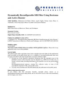
IV. T HE T OP - DOWN M ODELING M ETHODOLOGY Based on the requirements of the ideal methodology stipulated at the end of the previous section, this section proposes our top-down modeling methodology, which is built on top of ReChannel [6], [7], an open source SystemC library. Figure 1 provides an overview of the methodology. It should be noted that in this figure and all that follow, the simulationonly artifacts (open blocks) are virtual components covered in or extended from ReChannel to assist in the functional verification of the system, and real entities (solid blocks) are defined by users to be synthesized and mapped to the FPGA. Moreover, the lightly shaded parts perform the required computation defined by the functional specification, while the darkly shaded parts are modules added to the application to support dynamic reconfiguration.
During this stage, the designer should also consider the bitstream datapath, i.e. the path from the bitstream storage device to the reconfiguration port of the FPGA. For very simple designs, this datapath contains just some glue logic, while it can also become very complex, involving decompression, decryption and error checking (see for example, the bitstream datapath in [16]). Thus, Bug # 9. If the system uses a shared datapath for bitstream and application data streams, failure to correctly schedule the two streams may lead to bugs. The behavior of RMs during reconfiguration is highly dependent on their physical implementation such as the placement and routing of the old and new RMs. As has previously been discussed, this makes functional verification dependent on physical implementation, which is undesirable..
The proposed methodology takes the functional specification as input. Behavioral level modeling helps to explore all available design options. The TLM model assists in the verification of the execution flow of sub-modules and inter-module communications so as to support early system integration and the detection of global bugs. RTL modeling assists in the verification of the signal-level implementation of the modules so as to support the detection of local bugs. Finally, the RTL model is mapped to the FPGA device without further change.
AFTER reconfiguration: The time interval from just after the last byte of the bitstream is written until the new module is activated. In the last stage of reconfiguration, the designer should consider how to initialize the newly downloaded RM. The options include restoring the state or resetting the RM. Bugs undetected BEFORE reconfiguration (e.g., Bug #1, 4, 5 ) may affect the correct initialization of the RM now. Other potential bugs in this stage include:
The methodology is fully compatible with existing and mainstream EDA tools. Using an open source SystemC compiler and the ReChannel library, the behavioral and TLM models can be simulated on any machine with a C++ compiler such as Visual Studio. We use the mixed-language (HDL & SystemC) ModelSim simulator to perform cycle accurate simulation at the RTL level. The final synthesis and implementation use standard FPGA vendor tools such as ISE & PlanAhead.
Bug # 10. Without a proper reset operation, the state of the newly downloaded RM can be affected by the previous RM, especially if both RMs share the same physical area on the FPGA. Bug # 11. The time to assert reset is critical. The reset signal should be coordinated with the isolation mechanism to ensure no undefined behavior of the RM is propagated to the static part. Bug # 12. The state of a pipelined RM can only be initialized by feeding the pipelines with meaningful data, which is more difficult to design correctly than simply resetting a single FSM [14].
A. Behavioral Level The behavioral level model of DRS only assists in verifying the very abstract operations of the application and hides all the details of reconfiguration. As in Figure 2, the static part of the application communicates with the RM through the rc_portal, a MUX-like SystemC class. Without loss of generality, we assume that the application logic operates as a master while the RMs are slaves so as to simplify the discussion of the refinement process from the behavioral model to the RTL model. To increase development productivity, there is no clear boundary between the real entities and the
Given the challenges of functionally verifying a DRS, the ideal modeling methodology should cover all three stages of dynamic reconfiguration so as to accurately detect all instances of the above potential bugs in a design. For example, the
12
Functional Specification Real Entities
Behavioral level Modeling
B. Transaction Level
Simulation -only artifacts
At the transaction level (Figure 3), the designer should model the architecture of the system so as to verify the execution flow of sub-modules and the inter-module communication. Although it can make use of the same modeling language, a TLM model differs from a behavioral model as follows:
SC_MODULE
- design space exploration
RC_MODULE
Transaction level Modeling
- execution flow of sub-modules - inter-module communication
SC_MODULE
RC_MODULE
SC_MODULE
Application
RTL level Modeling
- signal level manipulation - implementation of sub-modules
HDL (VHDL/Verilog)
Reconfigurable Region
data_port.read() data_port.write()
data_port
controller.reconfigure(module_id)
RC_MODULE
HDL (VHDL/Verilog)
SC_MODULE(A)
x l ta r o p _ c r
Reconfiguration Controller
sync add-ons
SC_MODULE(B) sync add-ons
ctrl_port.unload()
Synthesis & Implementation Figure 1.
Modeling methodology overview
icap.download(bitstream)
Application
A.read() A.write() l a tr o p _ c r
rc.unload(A) rc.activate(B)
rc_control
Figure 3.
•
RC_MODULE(A)
RC_MODULE(B) rc_reconfigurable
portal.switch()
•
A.unload()
B.activate()
Figure 2.
Reconfiguration Port (eg. ICAP)
rc.unload(A)
rc_control
rc.activate(B)
Bitstream Storage
rc_reconfigurable B.read() B.write()
ctrl_port
bitstream = mem.read(addr)
simulation-only artifacts. Thus the reconfiguration controller (rc_control) is shown as a half-open half-solid box in the figure, because it performs both simulation-only operations such as switching between the RMs and real control operations such as unloading and activating the RMs. At this level of abstraction, all communication channels are modeled as function calls and it’s acceptable to use a compile-time defined reconfiguration delay. Please note that in this figure and all that follow, all arrows represent the direction of communication flows from masters to slaves, which may sometimes differ from the direction of data flows. portal.read() portal.write()
x
Behavioral modeling, after [6]
Despite making only limited contributions to detecting bugs, behavioral level modeling is useful for design space exploration to see whether it is worthwhile adopting dynamic reconfiguration as a strategy and for evaluating the available reconfiguration options BEFORE, DURING and AFTER reconfiguration as early as possible. These include, for example, whether the system should wait for the RM, kill the RM, or save the RM state BEFORE reconfiguration, and which operations the RM should preserve as atomic. After the desired options have been chosen, the behavioral model can be considered to be an executable, non-ambiguous specification of the DRS from which to proceed with the refinement process.
13
TLM modeling
Distinguishing between entities and artifacts All simulation-only artifacts (e.g., rc_portal, rc_control) are gathered and put into the reconfigurable region (RR), a virtual container that represents the reconfigurable area on the FPGA. A Data_port and a Ctrl_port form the abstract representations of the interface signals of the application logic and the reconfiguration add-ons, respectively. Note that the rc_control in the behavioral model is now modeled separately as an rc_control component, now contained in the RR, that performs simulationonly operations, a user-defined Reconfiguration Controller that performs real control operations, and the Reconfiguration Port that mimics the configuration resources of the FPGA. Modeling the execution flows The execution flow of the real entities should be explicitly modeled. For example, upon receiving a request to reconfigure a region, the Reconfiguration Controller unloads the current module (ctrl_port.unload()), and transfers the bitstream from the storage memory to the Reconfiguration Port (bitstream = mem.read(addr); icap.download(bitstream)); the Reconfiguration Port implicitly calls the rc_control to enable the new module as if the downloaded bitstream were written to the configuration memory of the FPGA. In this way, the designer can detect bugs that involve illegal operations such as conflicting reconfiguration requests of the controller (Bug #3), and in the bitstream datapath caused by bugs in the scheduling algorithm (Bug #9).
•
Modeling the inter-module communication In addition to delineating the partitioning and the execution flow of real entities, TLM is also concerned with inter-module communication channels, including the parameters of those channels. For example, ctrl_port.unload() does not take any parameter, which implies this operation only needs some handshaking signals such as req & ack. As another example, recording the flushed data, as mentioned in Bug #1, may require a register in the static part. Simulating the relevant function calls with the register as a parameter helps to detect Bug #1.
•
To conclude, in the TLM model, the architecture of the system should be clearly defined, including all the sub-modules and the communication channels between them. This helps to detect bugs involving illegal operations and incorrect interface parameters. With such a TLM model, the designers can then verify the integration of the system before the component details are available and thereby shorten the verification timeline. C. Register Transfer Level •
When moving to RTL modeling, as shown in Figure 4, the verified execution and communication flows of the TLM model need to be reproduced and mapped to signal-level protocols and the individual modules need to be implemented. on_open(){Ă} // connects signals as normal on_close(){Ă} // starts 'X' injection
sig_2staic_A
sig_2static
þxÿ
sig_2rm
Application
Reconfigurable Region
wire [31:0] data wire wr_en ...
wire [1:0] module_id; Reconfiguration Controller wire req, ack; wire reset; wire isolate;
wire [31:0] addr; wire [31:0] data; wire mem_rd_en;
d e d n et xE
n io t a l o s I
l at r op c_ r
sync add-ons
SC_MODULE(B) sync add-ons
Reconfiguration Port (eg. ICAP)
sc_signal req , ack;
•
rc_monitor
rc.activate(B) sc_signal req
Bitstream Storage
Figure 4. •
SC_MODULE(A)
x
x
wire [31:0] bit_data; wire bit_wr_en;
sig_2rm_A
sc_signal ack
wait(req_posedge & ack_posedge); rc_control::unload(current);
RTL modeling
Synchronization (sync.) To perform cycle-accurate simulation of synchronization BEFORE reconfiguration, we have derived a novel rc_monitor class from the rc_control to interface with the unloading operations of req & ack signals (see
14
the skeleton code in Figure 4). In this way, we can detect timing bugs such as not successfully stopping multiple FSMs or pipelines (e.g., Bug #2). Isolation (isol.) DURING reconfiguration, the designer should perform cycle-accurate simulation to verify the isolation mechanisms (e.g., the isolate signal and the Isolation module in Figure 4) and to detect, for example, Bugs #6, 7 and 8. In order to mimic the undefined behavior of an RM DURING reconfiguration, we have also derived a novel extended portal from the rc_portal. It overloads the member function on_open() & on_close(), which are implicitly called by the rc_monitor upon switching RMs so as to inject undefined (X) signals to the static side DURING reconfiguration (see the skeleton code in Figure 4). However, because RMs on FPGAs can output random instead of undefined values to the static part, X injection can only reveal the possibility of bugs and is of limited value in tracing the bug. A similar approach can be found in [14] where X injection is implemented using a VHDL MUX instead of using a SystemC class, as in ReChannel. Initialization (init.) In order to verify the initialization mechanisms, we need to mimic the undefined state of the RM AFTER reconfiguration. In Figure 4, the extended portal also injects undefined X into inactive RMs. These undefined values propagate into the internal wires and registers as well as towards the IOs of the RM, and are kept until the RMs are properly initialized when they are later swapped in. AFTER reconfiguration, internal X values mimic the undefined initial state of the new RM and help to detect Bugs #10 and 12, while X values on the IOs mimic undefined outputs to the static part and help to verify the timing of reset (e.g., Bug #11). However, for similar reasons as for isolation, this method can not accurately emulate the presence of real bugs and therefore only serves as a reference. The bitstream datapath At RTL level, the bitstream datapath should also be accurately simulated to verify, for example, the signals and FSMs of the scheduling algorithm (e.g., Bug #9). To detect bugs in the bitstream datapath, it may be insufficiently accurate to assume a compile-time defined reconfiguration delay. The Reconfiguration Port keeps track of the size of the bitstream written so far and should not allow the new RM to be activated until the amount of data transferred reaches the compile-time defined size of each RM. This allows the transfer of a bitstream to be interrupted if the bitstream datapath is shared with the application or if the datapath latency is dependent on run-time information (e.g., when decompressing or decrypting the bitstream). For simulation purposes, the size of the bitstream can be set to a small value for the sake of improving simulation performance.
from the XCTRL and the requests for memory access from the application as well as manipulating the reconfiguration port (ICAP) and the storage device (ZBT-SRAM). Note that the ICAP-I and the ZBT-SRAM are shared between the application and the reconfiguration add-ons and are thus both lightly and darkly shaded in the figure.
As mentioned above, some of the implementation-dependent design options of the DRS cannot be verified by functional simulation. For example, synthesizable HDL descriptions of the state saving and restoring logic can not directly access the internal registers and wires of an RM, which are also described using HDL. Saving and restoring state can only be simulated by modeling the configuration resources and access mechanisms of the FPGA and the configuration bitstreams of the design. Since the bitstreams are implementation dependent, they are not available at the time functional verification should be completed. Consequently, simulating these aspects of a design is not supported nor recommended and the relevant bugs (e.g., Bug #4, 5) cannot be detected in our methodology.
After exploring the design space at the highest behavioral level, we chose the “wait and sync” option BEFORE reconfiguration and the “simple reset” option AFTER reconfiguration. The behavioral level model used a block diagram similar to Figure 2, in which the real entities and the artifacts were not partitioned. We evaluated the execution and the communication of the system via a TLM model. In particular, we considered two candidates for the interface between the XCTRL and the ICAP-I. One option considered the interface function icapi_download(addr, size), which requests the ICAP-I to copy the bitstream from the given address in the ZBT-SRAM to the ICAP. The other option used the function icapi_download(cmd, para), whereby the cmd can be ICAPI_ADDR, ICAPI_SIZE or ICAPI_START, and needs three consecutive function calls to start a reconfiguration request. We chose the second approach to make the ICAP-I more generic at some cost of performance. The scheduling between the application and the bitstream datapath were simulated and verified at this level.
Table III summarizes the design choices and verification issues covered by the three levels of abstraction within our proposed methodology. V. A C ASE S TUDY We demonstrate the feasibility and indicate the value of using our top-down methodology via a case study involving the design of a general purpose dynamically reconfigurable computing platform. The architecture of the platform is similar to the Erlangen Slot Machine [16], which also implements the reconfigurable features of embedded and high-performance applications such as software defined radio [17] and OTN muxponder application [18]. To focus on the verification issues, we represent the essential elements of our platform as illustrated in Figure 5. Producer_HDL Consumer_HDL XCTRL
wire [31:0] data wire wr_en ... wire req, ack; wire reset; wire isolate;
FIFOs
Reconfigurable Region n io t la o s I
wire [1:0] cmd; wire [31:0] para;
ICAP-I
wire [31:0] bit_data; wire bit_wr_en; wire [31:0] addr; wire [31:0] data; wire mem_rd_en;
Figure 5.
Two students worked on the final refinement from TLM to RTL level. One student worked primarily on the ICAP-I while the other implemented the rest of the system. With the cycle accurate simulation of the RTL model, we detected 3 bugs that are relevant to the XCTRL: two synchronization timing bugs (similar to Bug #2) and one isolation timing design error (similar to Bug #11). By more accurately simulating the flow of the bitstream instead of assuming a compiletime defined reconfiguration delay, we also detected dozens of bugs in the ICAP-I scheduler (similar to Bug #9). Since the interface between the ICAP-I and the XCTRL was clearly defined and verified at the TLM level, the integration of the two students’ work was straightforward. The verified design was implemented and tested on a Virtex 4 LX160 FPGA on the ADM-XRC-4 evaluation board, and no more bugs were found.
Maximum_HDL Sync_HDL
Swap_HDL
Sync_HDL ICAP
ZBTSRAM
Case study
Comparing Figure 5 with Figure 4, the application logic is composed of Producer and Consumer modules, which keep sending/receiving data to/from the RM through two FIFOs, and reading/writing data from/to the memory through the ICAP-I. We use two alternative RMs: a Maximum module reads two data from the input FIFO and writes the larger one to the output FIFO; and a Swap module reads two data from the input FIFO and writes them to the output FIFO in the reverse order.
VI. C ONCLUSIONS As is the case in modern ASIC design, functional verification has become a significant challenge in FPGAs, and dynamic reconfiguration adds a new dimension to the challenge. To perform the most popular and traditional simulation-based functional verification, accurate modeling of the DRS is essential.
The reconfiguration controller is implemented using two separate entities: the XCTRL is responsible for synchronization, isolation and initialization of the RMs; and the ICAP-I module [19] schedules between the requests for reconfiguration
This paper addresses these modeling difficulties by bridging the gap from the very abstract, behavioral level modeling down to the RTL level that is to be mapped onto the FPGA.
15
Table III C OMPARING THE THREE LEVELS OF ABSTRACTION
BEFORE Recon.
DURING Recon.
AFTER Recon.
Behavioral Level
Choose the sync. option: - Kill the RM immediately - Wait for the RM - Save RM states
N/A
Choose the init. option: - Reset the RM - Restore RM states
Transaction Level
Verify the sync. interface: - The execution flow (e.g., Bug #3) - The parameters (e.g., Bug #1)
Integrating the bitstream datapath with the rest of the system: - The execution flow (e.g., Bug #9) - The parameters
Verify the init. interface: - The execution flow - The parameters (e.g., Bug #1)
RTL Level
Verify the signal-level manipulation for sync.: - The timing of sync.(e.g., Bug #2)
Verify the signal-level manipulation for isol. & bitstreams: - The timing of isol.(e.g., Bug #7) - The effect of the undefined RM (e.g., Bug #6,8) - The timing of the bitstream datapath (e.g., Bug #9)
Verify the signal-level manipulation for init.: - The timing of init.(e.g., Bug #11) - The effect of the old RM on the new RM (e.g., Bug #10,12)
Not covered
Implementation dependent options - Save RM states (e.g., Bug #4, 5)
N/A
Implementation dependent options - Restore RM states (e.g., Bug #4, 5)
By providing a complete, top-down modeling methodology (tools, guidelines and examples), future designers can follow a straightforward refinement process to facilitate early functional verification closure. We have also identified and analyzed a set of potential bugs typically found in DRS systems. The bugs are categorized according to the different stages of operation, namely BEFORE, DURING & AFTER reconfiguration. We assessed the feasibility of our method via a simple case study.
[9] A. V. Brito, M. Kuhnle, M. Hubner, J. Becker, and E. U. K. Melcher, “Modelling and Simulation of Dynamic and Partially Reconfigurable Systems using SystemC,” in VLSI (ISVLSI), IEEE Computer Society Annual Symposium on, 2007, pp. 35 – 40. [10] G. Beltrame, L. Fossati, and D. Sciuto, “High-Level Modeling and Exploration of Reconfigurable MPSoCs,” in Conference on Adaptive Hardware and Systems, 2008, pp. 330 – 337. [11] P.-A. Hsiung, C.-S. Lin, and C.-F. Liao, “Perfecto: A SystemC-based Design-space Exploration Framework for Dynamically Reconfigurable Architectures,” ACM Transactions on Reconfigurable Technology and Systems (TRETS), vol. 1, no. 3, p. 17, 2008. [12] A. Pelkonen, K. Masselos, and M. Cupak, “System-level Modeling of Dynamically Reconfigurable Hardware with SystemC,” in Parallel and Distributed Processing Symposium (IPDPS), International, 2003, p. 8. [13] I. Robertson, J. Irvine, P. Lysaght, and D. Robinson, “Improved Functional Simulation of Dynamically Reconfigurable Logic,” in Field Programmable Logic and Applications (FPL), International Conference on, 2002, pp. 541–574. [14] I. Robertson and J. Irvine, “A Design Flow for Partially Reconfigurable Hardware,” ACM Transactions on Embedded Computing Systems (TECS), vol. 3, no. 2, pp. 257–283, 2004. [15] L. Moller, I. Grehs, E. Carvalho, R. Soares, N. Calazans, and F. Moraes, “A NoC-based Infrastructure to Enable Dynamic Self Reconfigurable Systems,” in Reconfigurable Communication-Centric Systems-on-Chip (ReCoSoC), International Workshop on, 2007, pp. 22–30. [16] C. Bobda, M. Majer, A. Ahmadinia, T. Haller, A. Linarth, and J. Teich, “The Erlangen Slot Machine: Increasing Flexibility in FPGA-based Reconfigurable Platforms,” in Field-Programmable Technology (FPT), International Conference on, 2005, pp. 37 – 42. [17] P. Sedcole, B. Blodget, T. Becker, J. Anderson, and P. Lysaght, “Modular Dynamic Reconfiguration in Virtex FPGAs,” in Computers and Digital Techniques, IEE Proceedings, vol. 153, no. 3, 2006, pp. 157 – 164. [18] Increasing Design Functionality with Partial and Dynamic Reconfiguration in 28-nm FPGAs, v1.0 (wp01137) ed., Altera Inc., 2010. [Online]. Available: http://www.altera.com/literature/wp/wp01137-stxv-dynamic-partial-reconfig.pdf [19] V. Lai and O. Diessel, “ICAP-I: A Reusable Interface for the Internal Reconfiguration of Xilinx FPGAs,” in Field-Programmable Technology (FPT), International Conference on, 2009, pp. 357–360. [20] J. Aynsley, OSCI TLM-2.0 Language Reference Manual, Open SystemC Initiative (OSCI), 2009. [Online]. Available: http://www.systemc.org/home
Looking ahead, we plan to evaluate the impact of physical implementation on functional verification. Although it is desirable to hide the physical implementation and reconfigurable fabric during simulation, it is possible that some bugs may be missed. The consequences of ignoring these physical implementation details are not known. We are also looking at extending the TLM library [20] with reconfiguration support so as to ease the creation of the TLM model. R EFERENCES [1] K. Compton and S. Hauck, “Reconfigurable Computing: A Survey of Systems and Software,” ACM Computing Surveys (CSUR), vol. 34, no. 2, pp. 171–210, 2002. [2] D. Robinson and P. Lysaght, “Verification of Dynamically Reconfigurable Logic,” in Field Programmable Logic and Applications (FPL), International Conference on, 2000, pp. 141–150. [3] P. Bellows and B. Hutchings, “JHDL-an HDL for Reconfigurable Systems,” in Field-Programmable Custom Computing Machines (FCCM), IEEE Symposium on, 1996, pp. 175 – 184. [4] S. Singh, “Designing FPGA Circuits in Lava,” in VLSI Design (ICVD), International Conference on, 2004, pp. 299–306. [5] IEEE Standard 1666-2005: SystemC Language Reference Manual, The Institute of Electrical and Electronics Engineers, Inc. Std., 2005. [6] A. Raabe and A. Felke, “A SystemC Language Extension for High-Level Reconfiguration Modelling,” in Specification, Verification and Design Languages (FDL). Forum on, 2008, pp. 55 – 60. [7] A. Raabe, P. A. Hartmann, and J. K. Anlauf, “ReChannel: Describing and Simulating Reconfigurable Hardware in SystemC,” ACM Transactions on Design Automation of Electronic Systems (TODAES), vol. 13, no. 1, p. 15, 2008. [8] A. Schallenberg, W. Nebel, A. Herrholz, and P. A. Hartmann, “OSSS+R: A Framework for Application Level Modelling and Synthesis of Reconfigurable Systems,” in Design, Automation and Test in Europe (DATE), 2009, pp. 970 – 975.
16