2008 American Control Conference Westin Seattle Hotel, Seattle, Washington, USA June 11-13, 2008
FrA17.5
Neural Network Solution for Forward Kinematics Problem of HEXA Parallel Robot M. Dehghani, M. Ahmadi, A. Khayatian, M. Eghtesad and M. Farid
Similar to serial robots, kinematic analysis of parallel manipulators contains two problems: forward kinematics problem (FKP) and inverse kinematics problem (IKP). In parallel robots unlike serial robots, solution to IKP is usually straightforward but their FKP is complicated. FKP involves a system of nonlinear equations that usually has no closed form solution [5]. Traditional methods to solve FKP of parallel robots have focused on using algebraic formulations to generate a high degree polynomial or a set of nonlinear equations. Then, methods such as interval analysis [6], algebraic elimination [7], Groebner basis approach [8] and continuation [9] are used to find the roots of the polynomials or solve nonlinear equations. The FKP is not fully solved just by finding all the possible solutions. Schemes are further needed to find a unique actual position of the platform among all the possible solutions. Use of iterative numerical procedures [10] and auxiliary sensors [11] are the two commonly adopted schemes to further lead to a unique solution. Numerical iteration is usually sensitive to the choice of initial values and nature of the resulting constraint equations. The auxiliary sensors approach has practical limitations, such as cost and measurement errors. No matter how the forward kinematics problem may be solved, direct determination of a unique solution is still a challenging problem. Artificial neural networks (ANNs) are computational models comprising numerous nonlinear processing elements arranged in patterns similar to biological neural networks. These computational models have now become exciting alternatives to conventional approaches in solving a variety of engineering and scientific problems. Some researchers have tried using neural networks for solving the FKP of parallel robots [12-13]. Almost all prior researches have focused on using ANNs approach to solve FKP of Stewart platform. Few of them have also applied this method to solve FKP of other parallel robot [14-15]. In this paper, we focus on HEXA parallel robot, first presented by Pierrot [16], whose platform is coupled to the base by 6 RUS-limbs, where R stands for revolute joint, U stands for universal joint and S stands for
Abstract- Forward kinematics problem of parallel robots is very difficult to solve in comparison to the serial manipulators. This problem is almost impossible to solve analytically. Numerical methods are one of the common solutions for this problem. But, convergency of these methods is the drawback of using them. In this paper, neural network approach is used to solve the forward kinematics problem of the HEXA parallel manipulator. This problem is solved in the typical workspace of this robot. The results show the advantages of this method in providing very small modeling errors.
І. INTRODUCTION HE idea of designing parallel robots started in 1947 when D. Stewart constructed a flight simulator based on his parallel design [1]. Then, other types of parallel robots were introduced [2]. Parallel manipulators have received increasing attention because of their high stiffness, high speed, high accuracy and high carrying capability [3]. However, parallel manipulators are structurally more complex, and also require a more complicated control scheme; in addition, they have a limited workspace in compare to serial robots. Therefore, parallel manipulators are the best alternative of serial robots for tasks that require high load capacity in a limited workspace. A parallel robot is made up of an end-effector that is placed on a mobile platform, with n degrees of freedom, and a fixed base linked together by at least two independent kinematic chains [4]. Actuation takes place through m simple actuators.
T
Manuscript received March 26, 2008. M. Dehghani is a MSc student of Department of Electrical Engineering of Shiraz University, Shiraz, Iran (phone: +98-7112303051; fax: +98-711-628-7294; e-mail:
[email protected]). M.Ahmadi is a MSc student of Department of Mechanical Engineering of Shiraz university, Shiraz, Iran (e-mail:
[email protected]). A. Khayatian, Associate Prof. of Department of Electrical Engineering of Shiraz University, Shiraz, Iran (
[email protected]). M. Eghtesad, Associate Prof. of Department of Mechanical Engineering of Shiraz University, Shiraz, Iran (
[email protected]). M. Farid, Assistant Prof. of Department of Mechanical Engineering of Shiraz University, Shiraz, Iran (
[email protected]).
978-1-4244-2079-7/08/$25.00 ©2008 AACC.
4214
spherical joint. Complete description of HEXA robot is presented in Section 2. The solution of IKP of HEXA was first presented in [16] by F. Pierrrot who solved the system of nonlinear equations and obtained a unique solution for the problem. A numerical solution for FKP of parallel robot was presented by J.P. Merlet in [5]. FKP of this robot has no closed form solution and at most 40 assembly modes (assembly modes are different configurations of the endeffecter with given values of joint variables) exist for this problem. He suggested iterative methods for solving HEXA FKP. But, these methods have some drawbacks, such as being lengthy procedures and giving incorrect answers [5]. Utilization of the passive joint sensors; however, enables one to find closed form solutions. In [17] it has been shown that a minimum number of three passive joint sensors are needed for solving the FKP analytically. In this paper, neural network approach is used to solve FKP of HEXA robot. To carry out this task, we first estimate the IKP in some positions and orientations of the workspace of the robot. Then a multilayer perceptron (MLP) network is trained with data obtained by solving IKP. Finally, we test the network in the other positions and orientations of the workspace. The rest of the paper is organized as follows: Section 2 contains HEXA mechanism description. Kinematic modeling of the manipulator is discussed in Section 3 where inverse and forward kinematics are studied and the need for appropriate method to solve forward kinematics is justified. Neural network method to solve FKP is discussed in Section 4. In Section 5 the results of solving FKP for HEXA robot are presented.
Consequently, HEXA enjoys the advantages of faster motions, better accuracy, higher stiffness and greater loading capacities over the serial manipulators [22].
ІІ. MECHANISM DESCRIPTION There are different classes of parallel robots. Undoubtedly, the most popular member of the 6-RUS class is the HEXA robot [16], of which an improved version is already available. The first to propose this architecture, however, was Hunt in 1983 [18]. Some other prototypes have been constructed by Sarkissian [19], by Zamanov [20] and by Mimura [21]. The latter has even performed a detailed set of analyses on this type of manipulator. Two other designs are also commercially available by Servos & Simulation Inc. as motion simulation systems [5]. Finally, a more recent and more peculiar design has been introduced by Hexel Corp., dubbed as the “Rotary Hexapod” [5]. Among these different versions, Pierrrot’s HEXA robot is considered in this paper. All types of HEXA robots are 6-DOF parallel manipulators that have the following characteristics: a) With multiple closed chains, it can realize a greater structural stiffness. b) To prevent the angular error of each motor from accumulating, it can realize a higher accuracy of the endeffecter position. c) As all the actuators can be placed collectively on the base, it can realize a very light mechanism.
Ribi is the rotation matrix between the base frame {bs}
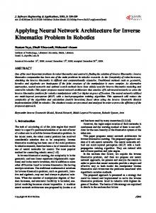
ІІІ. KINEMATIC MODELING As in the case of conventional serial robots, kinematics analysis of parallel manipulators is also performed in two phases. In forward or direct kinematics the position and orientation of the mobile platform is determined given the leg lengths. This is done with respect to a base reference frame. In inverse kinematics we use position and orientation of the mobile platform to determine actuator lengths. For all types of parallel robots, IKP is easily solved. For HEXA parallel robot this problem was solved by Pierrrot [16]. Brief solution of IKP is presented by Bruyninckx in [23]. Fig. 1 shows one mechanical chain in HEXA design. In each chain, M specifies the length of the crank which is the mechanical link between the revolute and universal joints, and L gives the length of the rod which connects universal and spherical joints. Other parameters, H and h, are introduced as shown in Fig. 1; a is the length of a side of the traveling platform, The relationship between the joint angles Өi,j (i=1,2,3 and j=1,2), robot parameters and position and orientation of the end-effector can be obtained from the following procedure. The joint angle Өi,j moves the end point of crank of ith leg to the position pi given by
pi = bi + R ibiR ( X , θ i , j )[0 0 M ]
T
(1)
In this equation, the joint angle Өi,j is the only unknown variable. The positions pi are connected to a mobile platform pivot point ti by links of known length L. Matrix and a reference frame constructed in the actuated R joint, with X-axis along the joint axis and the Z-axis along the direction of the first link corresponding to a zero joint angle Өi,j (see Fig. 1). Matrix R(X, Өi,j) is the rotation matrix corresponding to a rotation about the X axis by the angle Өi,j: ⎡1 ⎤ 0 0 ⎢ ⎥ R( X ,θ i , j ) = ⎢0 cos(θ i , j ) − sin(θ i , j )⎥ ⎢0 sin(θ ) cos(θ ) ⎥ i, j i, j ⎦ ⎣
(2)
In each chain, a loop closure formulation can be adopted as follows (see Fig. 1): ti bi = ti pi + pi b i
(3)
with
4215
bi pi = M
(4)
ti pi = L
(5)
knowledge is represented as numeric weights, which are used to gather the relationships within data that are difficult to relate analytically, and this iteratively adjusts the network parameters to minimize the sum of squared approximation errors using a gradient descent method. Neural networks can be used to model complex relationship without using simplifying assumptions, which are commonly used in linear approaches. One of its implementation types is back propagation network that is trained with supervision, using gradient-descent training technique which minimizes the squared error between the actual outputs of the network and the desired outputs.
By substitution of cos(Өi,j) = (1 − t^2)/(1+ t^2) and sin(Өi,j) = 2t/(1 + t^2) in the above equations, it is possible to solve (3), (4), (5), for Өi,j : θ i, j = 2 * tan −1 (
Vi , j ± Vi , j 2 − Wi , j 2 + U i , j 2 U i , j + Wi , j
(6)
)
where
Vi , j = − µ
(7)
i.j
U i , j = λi , j − H Wi, j =
(8)
L2 − M2 +(λi, j − H)2 +(ρi, j −
(−1) j a 2 ) + µi, j 2 2
(9)
2L
h
ψ
Traveling platform
Ө L
ti
φ
pi
Z Өi,j H
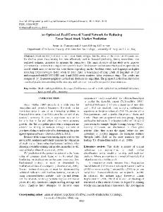
Multilayer perceptron (MLP) Multilayer perceptron neural networks with sufficiently many nonlinear units in a single hidden layer have been established as universal function approximators. MLP have several significant advantages over conventional approximations. First, MLP basis functions (hidden unit outputs) change adaptively during training, making it unnecessary for the user to choose them beforehand. Second, the number of free parameters in the MLP can be unambiguously increased in small increments by simply increasing the number of hidden units. Third, MLP basis functions are bounded which make round-off and overflow errors unlikely, [24]. The MLP is one of the typical back propagation ANNs and consists of an input layer, some hidden layers and an output layer, as shown in Fig. 2.
M
Y
bi X
Base platform
Fig. 1. A typical chain of the HEXA design. The joint angle Өi,j is variable and measured; the lengths L and M of the “base” and “top” limbs of each chain are constant; the angles of all other joints are variable but not measured.
Fig. 2. Schematic of the MLP network [12].
and [λi , j ρ i , j µ i , j 1]T is the position vector of the pivot point ti in the reference frame constructed in the actuated R joint [16].The same equations can be used to derive the HEXA forward kinematic model, but the closed form solution to FKP can not be found. So, we propose to use numerical schemes by neural network approach for solving FKP in the workspace of the robot.
MLP is trained by back propagation of errors between desired values and outputs of the network using gradient descent or conjugate gradient algorithms. The network starts training after the weight factors are initialized randomly. Valid data consisting of the input vector and the corresponding desired output vector is fed to the network and the difference between the output layer result and the corresponding desired output result is used to adjust the weights by back propagation of the errors. This procedure continues until errors are small enough or no more weight changes occur. A first challenge in training the back propagation neural network is the choice of the appropriate network architecture, i.e. number of hidden layers and number of nodes of each layer. There is no available theoretical result which such choice may rely
IV. ARTIFICIAL NEURAL NETWORK The inspiration for neural networks comes from researches in biological neural networks of the human brains. Artificial neural network (ANN) is one of those approaches that permit imitating of the mechanisms of learning and problem solving functions of the human brain which are flexible, highly parallel, robust, and fault tolerant. In artificial neural networks implementation, 4216
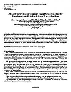
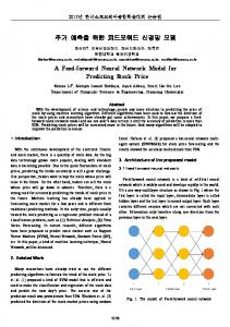
over 1200 epochs with error back propagation training. Each network is evaluated by comparing the predictions to the true outputs, resulting in a prediction error for each orientation angle. The autocorrelation coefficients are also computed for the predicted error of each orientation angle. It should be noted that in order to avoid local minima, the trained weights in the last step are used in each step. C. Modeling results Fig. 3 and Fig. 4 show the results of FKP solution by MLP; Table 2 shows the resulted errors of FKP modeling. It is apparent from Table 2 that mse, mae and nrmse in all joints are less than 2e-5, 0.01 and 0.01 respectively, in test data. mae indicates maximum absolute error of modeling; therefore, maximum error of position and orientation of mobile platform is not bigger than 1 millimeter in position and 0.1 degrees in orientation in worse case. mse shows the maximum of the average of errors in all points and so the average error of FKP solution in the typical workspace is less than 2e-5. R in table 2 indicates linear regression between output of the network and target data. The closer regression to 1, the better the modeling is. The linear regression of all joints is more than 0.99 which shows very good modeling results. Fig. 4 shows the error of modeling in 1000 sample test points of typical workspace. For these sample points the errors of modeling in position and orientation are very small and can be neglected.
on. This can only be determined by user’s experience [24].
V. NEURAL NETWORK SOLUTION FOR FKP In order to model the FKP with ANNs, first, typical workspace of the robot is determined. Then, IKP is solved in some poses of the workspace and finally ANNs is trained with the data of IKP solution in typical robot workspace. A. Workspace analysis It is well known that parallel manipulators have a rather limited and complex workspace. Six parameters consisting of three coordinates of position of center of mass of mobile platform in the base frame (X, Y, Z) and three RPY orientation angles of mobile platform with respect to the base frame (three angles of mobile platform orientation in space consist of φ, ψ and Ө angles, see Fig. 3) vary in the HEXA workspace. Complete analysis of HEXA workspace is presented in [25] by A. Bonev. We use a typical workspace in which end-effector can move 300 millimeters in both directions of X and Y axes; also it can move 600 millimeters in positive Z direction. In all positions of the workspace, mobile platform can rotate in the range of [-π/3 π/3] by φ, ψ and Ө angles. The geometric parameters of the robot were given in Table 1. Table 1. Geometric parameter of HEXA parallel robot
H 360mm
H 51mm
M 220mm
L 280mm
A 51mm
VI. CONCLUSION In this paper, artificial neural network (MLP network) is used for FKP solution of HEXA parallel robot which can be elaborated to generate the best estimation of orientation and position of the mobile platform. The research results in this paper are interesting because they solve a problem for which, there is no known closed form solution. So ANNs improve the parallel robot pose accuracy. Since, a back propagation network can learn highly nonlinear functions and has been applied successfully to approximate the complex mapping between robot positions and orientations and robot joints angles.
B. Neural network solution for FKP Now MLP network will be trained with the data generated by solution of IKP. In order to model the FKP in terms of 6 variables of position and orientation of the mobile platform, an MLP neural network with configuration of 6×13×13×13×13×13×6 has been found to have the smallest error and has been used to model FKP. In other words, the ANN model has 6 inputs consisting of 6 joint angles, 5 hidden layers which have 13 neurons and 6 neurons in the output layer. Note that the activation functions used in the hidden layers and output layer are logarithmic and pure linear, respectively. The number of patterns used for training and test are 17500 and 35000, respectively. The network is trained
Table 2. The resulted errors of FKP modeling by test data
Variable
mse
mae
nrmse
R
X
1.3232e-005
0.0089
0.01
0.999
Y
5.76992e-006
0.0076
0.0094
0.999
Z
1.79034e-005
0.0091
0.0045
0.999
φ
5.77768e-006
0.01
0.0073
0.988
Ө
1.20364e-006
0.009
0.0034
0.988
ψ
2.1676e-006
0.0087
0.0045
0.999
4217
Fig. 3-d
Fig. 3-a
Fig. 3-b
Fig. 3-e
Fig. 3-c
Fig. 3-f
Fig. 3. The results of HEXA parallel robot modeling with ANN for X,Y,Z axes and φ, ψ , Ө angles, respectively from 3-a to 3-f. -3
Error of modeling position in X axis
6
0.015
Error of modeling position in Y axis
x 10
4
0.01
error of modeling
error of modeling
2 0.005
0
-0.005
-0.01
0
-2
-4
0
200
400
600 Samples number
800
1000
-6
1200
Fig. 4-a
0
200
400
600 Samples number
800
Fig. 4-b
4218
1000
1200
-3
-3
Error of modeling position in Z axis
x 10
6
6
4
4
2
2
0 -2 -4 -6
Error of modeling position in TETA angle
x 10
8
error of modeling
error of modeling
8
0 -2 -4 -6
-8
-8
-10
-10
0
200
400
600 Samples number
800
1000
1200
0
200
400
Fig. 4-c
600 Samples number
800
1000
1200
Fig. 4-e -3
Error of modeling position in FI angle 0.015
8
Error of modeling position in SAI angle
x 10
6
0.01
4 2 error of modeling
error of modeling
0.005
0
-0.005
0 -2 -4 -6 -8
-0.01
-10
-0.015
0
200
400
600 Samples number
800
1000
-12
1200
0
200
400
600 Samples number
800
1000
1200
Fig. 4-f
Fig. 4-d
Fig. 4. The error of HEXA parallel robot modeling with ANN for X,Y,Z axes and φ, ψ , Ө angles, respectively from 4-a to 4-f. [14] A.Ghobakhloo and M. Eghtesad,” Neural network solution for the forward kinematics problem of a redundant hydraulic shoulder,” EICON, 2005. [15] H. Sadjadian, H.D. Taghirad and A. Fatehi,’ Neural network solution for computing the forward kinematic of a redundant parallel manipulator,” Inte. J. of Comp. Int., Vol. 2, No. 1, 2005. [16] F. Pierrot, M. Uchiyama, P. Dauchez and A. Fournier,” A new design of a 6-DOF parallel robot,” J. Robotics and Mechatronics, Vol. 2, No. 4, 1990. [17] P. Last, C. Budde , C. Bier and J. Hesselbach,’ HEXA-parallelstructure calibration by means of angular passive joint sensors’, Proc. of the IEEE Int. Conf. on Mecha. and Auto., July 2005. [18] K.H. Hunt ,’Structural kinematic in parallel actuated robot arms,” J. of Mechanisms, Transmissions and Auto. in Design, 1983. [19] Y.L. Sarkissian and T.F. Parikyan, ”Manipulator,” 1990, Russion Patent, n1585144. [20] V.B. Zamanov and Z.M. Sotirov, “parallel manipulators in robotics,” Int. Symp. on Robotic, Mechat. and Manu. Syst., 1992. [21] N. Mimura and Y. Funahashi, “A new analytical system applying 6 dof parallel link manipulator for evaluating motion sensation,” IEEE ICRA, Nagoya, 1995. [22] M. Uchiyama, K. Iimura, F. Pierrot, K. Unno, and 0. Toyama, “Design and control of a very fast 6-DOF parallel robot,” Proc. of the IMACS/SICE Int. Symp., pp. 473-478, 1992. [23] H. Bruyninckx. ,“The HEXA: A fully-parallel manipulator with closed form position and velocity kinematic” Int. Conf. Robotics and Automation, pages 2657–2662, Albuquerque, NM, 1997. [24] L. Medsker and J. Liebowitz, "Design and Development of Expert Systems and Neural Networks,” Macmillan, New York, 1994. [25] I.A. Bonev and M. Gosselin, “A genetic algorithm for the computation of the constant orientation workspace of 6 RUS parallel manipulator,” DETC’00 ASME , 2000.
REFERENCES [1] [2] [3] [4] [5] [6] [7] [8] [9] [10] [11] [12] [13]
D. Stewart, “A platform with six degrees of freedom,” Proceedings of the Inst. Mech. Engr. 1965. J.P. Merlet, “Direct kinematic of planer parallel manipulator,” Proc. In IEEE ICRA, Minneapolis, 1996. J.P. Merlet, “Still a long way to go on the road for parallel mechanisms", ASME 2002 DETC Conf., .Montreal, 2002. L.W. Tsai, Robot Analysis (The Mechanics of Serial and Parallel Manipulators), John Wiley & Sons, Inc., 1999. J.P. Merlet, Parallel Robots (Solid Mechanics and Its Applications), Kluwer Academic Publishers, 2001. J.P. Merlet, “Solving the forward kinematics of a Gough-type parallel manipulator with interval analysis,” Int. J. Robot. 2004. T.Y. Lee and J. K. Shim, “Forward kinematics for the general 6- 6 Stewart platform using algebraic elimination,” Mech.Theory, 36, 1073–1085. J.P. Merlet, “Solving the forward kinematics of a Gough-type parallel manipulator with interval analysis,” The Int. Journal of Robotics Research, Vol. 23, No. 3, March 2004. M. Raghavan, “The Stewart platform of general geometry has 40 configurations,” ASME Design and Auto. Conf. Chicago, 1991. J.P. Merlet, “Direct kinematics of parallel manipulators,” Robotica, Vol. 25, 2007. L. Baron and J. Angeles, “The direct kinematics of parallel manipulators under joint-sensor redundancy,” IEEE Trans..Robot. Autom., 2000. Z. Geng and L. S. Haynes, “Neural network solution for the forward kinematics problem of a Stewart platform,” Robot. Comput. .Integrat. Manuf., 9(6), 485–495, 1992. C. S. Yee, “Forward kinematics solution of Stewart platform using neural networks,” Neurocomputing 16(4), 333–349, 1997.
4219