PHYSICS OF PLASMAS
VOLUME 8, NUMBER 5
MAY 2001
Improved plasma performance on Large Helical Device* A. Komori,†,a) N. Ohyabu, H. Yamada, O. Kaneko, K. Kawahata, N. Ashikawa,b) P. deVaries, M. Emoto, H. Funaba, M. Goto, K. Ida, H. Idei, K. Ikeda, S. Inagaki, N. Inoue, M. Isobe, S. Kado, K. Khlopenkov, T. Kobuchi,b) S. Kubo, R. Kumazawa, Y. Liang,b) S. Masuzaki, Y. Matsumoto,c) T. Minami, J. Miyazawa, T. Morisaki, S. Morita, S. Murakami, S. Muto, T. Mutoh, Y. Nagayama, Y. Nakamura, H. Nakanishi, K. Narihara, Y. Narushima, K. Nishimura, N. Noda, T. Notake,d) S. Ohdachi, Y. Oka, M. Okamoto, M. Osakabe, T. Ozaki, R. O. Pavlichenko, B. J. Peterson, A. Sagara, K. Saito,d) S. Sakakibara, R. Sakamoto, H. Sasao,b) M. Sasao, K. Sato, M. Sato, T. Seki, T. Shimozuma, M. Shoji, H. Suzuki, M. Takechi, Y. Takeiri, N. Tamura,b) K. Tanaka, K. Toi, T. Tokuzawa, Y. Torii,d) K. Tsumori, I. Yamada, S. Yamaguchi, S. Yamamoto,d) M. Yokoyama, Y. Yoshimura, K. Y. Watanabe, T. Watanabe, T. Watari, Y. Hamada, K. Itoh, K. Matsuoka, K. Ohkubo, T. Satow, S. Sudo, K. Yamazaki, O. Motojima, and M. Fujiwara National Institute for Fusion Science, Toki 509-5292, Japan
共Received 25 October 2000; accepted 4 December 2000兲 Since the start of the Large Helical Device 共LHD兲 experiment, various attempts have been made to achieve improved plasma performance in LHD 关A. Iiyoshi et al., Nucl. Fusion 39, 1245 共1999兲兴. Recently, an inward-shifted configuration with a magnetic axis position R ax of 3.6 m has been found to exhibit much better plasma performance than the standard configuration with R ax of 3.75 m. A factor of 1.6 enhancement of energy confinement time was achieved over the International Stellarator Scaling 95. This configuration has been predicted to have unfavorable magnetohydrodynamic 共MHD兲 properties, based on linear theory, even though it has significantly better particle-orbit properties, and hence lower neoclassical transport loss. However, no serious confinement degradation due to the MHD activities was observed, resolving favorably the potential conflict between stability and confinement at least up to the realized volume-averaged beta 具典 of 2.4%. An improved radial profile of electron temperature was also achieved in the configuration with magnetic islands, minimized by an external perturbation coil system for the Local Island Divertor 共LID兲. The LID has been proposed for remarkable improvement of plasma confinement like the high 共H兲 mode in tokamaks, and the LID function was suggested in limiter experiments. © 2001 American Institute of Physics. 关DOI: 10.1063/1.1344561兴
plasma control.7,8 The LID is a closed divertor that uses an m/n⫽1/1 island. A perturbation coil system was installed in LHD in order to generate a clear m/n⫽1/1 island at the /2 ⫽1 surface. The perturbation coil system can also be used to eliminate islands generated by error fields.7 The LHD experiment has progressed mainly by increasing the toroidal magnetic field B t and the heating power since the start of the LHD experiment. In the early campaigns, B t was set at 1.5 T so as to accumulate operational experience of the superconducting coils.3 It was raised up to about 2.9 T at the end of the 1999 campaign, which was almost equal to the rated field of 3 T. Hereafter, plasma parameters will be improved by a gradual increase in the heating power,9 obeying a scaling law, for example, the International Stellarator Scaling 95 共ISS95兲, which was derived based on the medium-sized helical devices.10 However, LHD aims at a remarkable improvement of plasma confinement like the high 共H兲 mode in tokamaks,11 which is much better than the present scaling.10 Therefore, various attempts have started in order to achieve this target and study the related physics. A temperature pedestal has been found to enhance the global energy confinement, which exhibits a sharp gradient at the edge of the electron temperature T e profile inde-
I. INTRODUCTION
The Large Helical Device 共LHD兲1–6 offers a great opportunity to study currentless plasmas, aiming at a steadystate heliotron-type fusion reactor. LHD has a major radius R of 3.9 m and a minor radius a of 0.65 m. Full steady-state operation is expected, using superconducting coils in addition to a full helical divertor. Steady-state plasma operation that is essential to magnetic fusion reactors is an inherent advantage of heliotrons over tokamaks and can be realized with the closed full helical divertor because it removes heat flux from the core plasma and controls impurity recycling. However, since it will not be ready in the near future, we plan to use the Local Island Divertor 共LID兲 for the LHD edge *Paper UI1 2, Bull. Am. Phys. Soc. 45, 289 共2000兲. † Invited speaker. a兲 Electronic mail:
[email protected] b兲 Permanent address: Department of Fusion Science, School of Mathematical and Physical Science, Graduate University for Advanced Studies, Hayama 240-0193, Japan. c兲 Permanent address: Division of Quantum Energy Engineering, Graduate School of Engineering, Hokkaido University, Sapporo 060-8628, Japan. d兲 Permanent address: Department of Energy Engineering and Science, Nagoya University, Nagoya 464-8603, Japan. 1070-664X/2001/8(5)/2002/7/$18.00
2002
© 2001 American Institute of Physics
Downloaded 16 Feb 2009 to 133.75.139.172. Redistribution subject to AIP license or copyright; see http://pop.aip.org/pop/copyright.jsp
Phys. Plasmas, Vol. 8, No. 5, May 2001
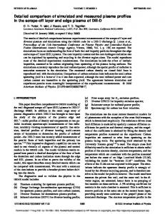
FIG. 1. Temporal behaviors of stored energy W p , averaged electron density ¯n e and radiation power P rad with ICRF heating applied to the NBI discharge.
pendently of the magnetic configuration.12,13 The pedestal realized an enhancement factor of about 1.15 in the standard configuration over the ISS95,14 but is considered to be small compared with the enhancement factor required for achieving our goal. Experiments in the magnetic configurations with different magnetic axis positions R ax’s and with minimized magnetic islands have been performed recently. The magnetic islands, which are generated by the error field, exist even in the high B t region in LHD, and hence the error field is considered to be larger than the terrestrial magnetism. An inward-shifted configuration with R ax⫽3.6 m showed much better plasma performance than the standard configuration with R ax⫽3.75 m. Remarkable progress has also been made in the ion cyclotron range of frequencies 共ICRF兲 heating in the inward-shifted configuration. The configuration with the islands minimized by the perturbation coil system for the LID was also found to be effective to achieve a better radial T e profile. The effects of the LID configuration on plasma performance were also examined in the limiter discharges to demonstrate LID functions for the edge plasma control, leading to a significant improvement of plasma confinement. In this paper we intend to describe such experimental results relevant to the improved plasma performance, demonstrated mainly in the last campaign. II. EFFECT OF MAGNETIC AXIS POSITION ON PLASMA PERFORMANCE
Figure 1 shows temporal evolution of a typical LHD discharge, produced by the standard heating scenario, initiating plasma by electron cyclotron heating 共ECH兲 and sustaining it by neutral beam injection 共NBI兲. ICRF was considered as an assistance of ion heating and was also expected to initiate plasma at an off-resonant B t . Figure 2 shows stored energies W p ’s as a function of shot number, representing the progress in the LHD plasma performance. Three large jumps in Fig. 2 correspond to the start of the NBI experiments, the increase in B t from 1.5 to over 2.5 T and the adoption of the
Improved plasma performance on Large Helical Device
2003
FIG. 2. Dependence of W p on shot number, representing progress in LHD plasma performance. A, B and C correspond to the start of NBI experiments, the increase in B t from 1.5 to over 2.5 T and the adoption of inward-shifted configuration, the start of efficient ICRF heating and Ti gettering, respectively.
inward-shifted configuration, and the start of the efficient ICRF heating and Ti gettering, respectively. A shot-by-shot increase in W p is attributed mainly to a gradual increase in the NBI power. The low W p ’s were obtained in the plasmas produced by ECH alone. The highest W p of 0.88 MJ was achieved by a hydrogen-pellet injector, which can inject a series of five pellets at intervals of 1 ms to 1 h. The plasma parameters achieved up to now are summarized as follows: 共1兲 T e of 4.4 keV, the ion temperature T i of 2.7 keV, the energy confinement time E of 0.06 s and the averaged electron density ¯n e of 5.3⫻1018 m⫺3 at the absorbed heating power P abs of 1.8 MW; 共2兲 T i of 3.5 keV, T e of 3.3 keV, E of 0.09 s and ¯n e of 1.0⫻1019 m⫺3 at P abs of 3.9 MW; 共3兲 E of 0.3 s, n i (0) T i (0) of 2⫻1019 keV m⫺3 s, T e of 1.1 keV and ¯n e of 6.5⫻1019 m⫺3 at P abs of 2.0 MW; 共4兲 具典 of 2.4%; and 共5兲 the maximum ¯n e of 1.1⫻1020 m⫺3. The maximum ¯n e was also obtained by the pellet injector. Although a variety of magnetic configurations can be studied in LHD, behaviors only in the configurations with R ax⫽3.9, 3.75, and 3.6 m, whose toroidal averaged ellipticity was 1, were studied, because divertor legs miss carbon divertor plates in the other configurations outside this R ax range. In the early campaigns, we concentrated our efforts on the configuration with R ax⫽3.75 m, which is the standard configuration optimized taking account of particle orbits and magnetohydrodynamic 共MHD兲 stability. The configuration with an inner R ax has been predicted theoretically to have significantly better particle-orbit properties and a larger volume of the plasma confining region than the standard one, but have unfavorable MHD properties, i.e., low-具典 limit due to magnetic hill geometry. Figure 3 shows the Mercier stability diagram,15 obtained by linear theory in the LHD configuration. Here, is a normalized minor radius. The broken lines represent the boundaries between the well and hill configurations for R ax⫽3.6 and 3.75 m. In the standard configuration, the unstable region is localized only in the peripheral
Downloaded 16 Feb 2009 to 133.75.139.172. Redistribution subject to AIP license or copyright; see http://pop.aip.org/pop/copyright.jsp
2004
Phys. Plasmas, Vol. 8, No. 5, May 2001
Komori et al.
FIG. 3. Contour map of normalized Mercier stability criterion for configurations at R ax⫽3.75 m and 3.6 m. Broken lines represent the boundaries between the well and hill configurations for R ax⫽3.6 and 3.75 m.
region. On the other hand, the plasma is unstable at R ax ⫽3.6 m against the ideal interchange mode in almost the whole plasma region. This is the reason that the configuration with R ax⫽3.75 m was selected as the standard one. Only a small number of discharges were performed in the outward-shifted configuration with R ax⫽3.9 m, but the plasma performance was found to be the worst of these three configurations, as expected. Figure 4 shows the 具典 dependence of root-mean-square fluctuation amplitudes of the global modes with m⭐3, observed in the NBI discharges at R ax⫽3.6 m and B t ⫽0.75– 1.5 T. The fluctuations were sampled at 50 kHz and normalized by the vacuum magnetic field B 0 at the probe position. The most important result in the high- experiment was that no serious confinement degradation was observed in the inward-shifted configuration even in the 具典 range up to
FIG. 4. Volume-averaged beta 具典 dependence of coherent magnetic fluctuation amplitudes, normalized by a vacuum magnetic field B 0 at the probe position.
FIG. 5. Heating power dependence of 共a兲 radial electron temperature T e and 共b兲 electron density profiles.
2.4%.16 The fluctuation amplitudes of m/n⫽1/2, 2/2 and 3/3 modes at the /2 ⫽1 increase with 具典, and reach about 10⫺4 when 具典 approaches 2.2%. Whether the fluctuation amplitude is saturated against 具典 or not, is not clear in this figure. The 2/1 mode at /2 ⫽1/2 appears when 具典 exceeds about 0.3%, and its amplitude increases with 具典. The 2/1 mode affects the T e profile, but does not the global plasma confinement.16 It was also found that the increase in the  gradient at ⫽0.5 was larger in the 具典 range of ⭓0.5% than ⬍0.5%, corresponding to the appearance of the m/n⫽2/1 mode. The existence of the threshold for instability is consistent with the linear analysis of the interchange mode. However, there is no threshold 具典 for the excitation of the /2 ⫽1 resonant modes at ⫽0.9, as mentioned above. Thus, theoretical approaches are required to explain the observations in addition to further experiments. A unique feature of the LHD plasma is the formation of a temperature pedestal, as shown in Fig. 5共a兲,12,13 where ¯n e of 4.4⫻1019 m⫺3 is kept constant, independently of the NBI power. Figure 5共b兲 shows the electron density n e profiles, corresponding to the T e profiles in Fig. 5共a兲. The width of the pedestal is 0.1–0.15 in , which is much wider than that of comparable tokamaks.11,17 The observed maximum pedestal (T ped is the electron temperature at temperature T ped e e ⫽0.85) is about 1 keV. Thus, the pedestal T ped e is very high, considering that it is 30%–50% of the central temperature, so that T ped e affects W p and hence E , as will be shown later. The formation of the pedestal takes place during the rising phase of discharges in all configurations used in our experiments, and is carried out without a rapid transition observed in the tokamak H-mode discharges, as shown in Fig. 1. The shrunken plasma generated by ECH expands with the NBI
Downloaded 16 Feb 2009 to 133.75.139.172. Redistribution subject to AIP license or copyright; see http://pop.aip.org/pop/copyright.jsp
Phys. Plasmas, Vol. 8, No. 5, May 2001
heating. Then the hot-plasma region reaches the last closed and the divertor flux flux surface 共LCFS兲, increasing T ped e during 10–20 ms. The existence of a pedestal is usually recognized as a bend in the T e profile, especially, in the standard configuration. The cold plasma exists outside the LCFS, and n e at ⫽1.0 is almost equal to that at the plasma center in the standard configuration, while it is almost half of the center n e in the inward-shifted configuration, as shown in Fig. 5共b兲. Thus, T e and n e profiles depend on the magnetic configuration. The effect of pedestal pressures on the confinement was studied using the NBI discharges in the standard configuration. Parameter regions cover B t of 1.5–2.5 T, ¯n e of (1.0 ⫺4.9)⫻1019 m⫺3, and P abs of 0.75–3.2 MW. The database consists of the hydrogen discharges in quasi-steady state. A comparison of these data with the ISS95 indicates a systematic enhancement of confinement with an enhancement factor of about 1.15. Figure 6共a兲 depicts E ’s, represented by closed circles when obtained in the standard configuration, and the 0.4 0.59 ¯ 0.51 ISS95, EISS95⫽0.079a 2.21R 0.65B 0.83 ( /2 ) 2/3 . t n e P abs The energy confinement time E was evaluated using W p from the diamagnetic loops. In estimating W p from the diamagnetic signal, we use the data, numerically calculated by the three-dimensional 共3D兲 magnetic field analysis with 3D finite- equilibrium. The NBI deposition profiles were evaluated using a Monte Carlo simulation code, MCNBI.18 A confinement region is assumed to be divided into the core and pedestal regions, and the core value should be compared with the scaling. The core value is defined by the subtraction of the pedestal at ⬃0.85 from the total value. A statistical analysis of the data from the combination of the core confinement in the standard configuration and the whole confinement of the medium-sized heliotrons 关H–E, ATF 共Advanced Toroidal Facility兲 and CHS 共Compact Helical System兲兴, in which the pedestal is not significant, gives the Escl2⫽0.059a 2.24 fitting expression of 0.39 0.67 0.81¯ 0.54 ⫺0.63 ⫻R B t n e P abs ( /2 ) 2/3 . The energy confinement times derived from the core values of W p agree quite well with this scaling, as shown in Fig. 6共b兲. In conclusion, the enhancement of the confinement in the standard configuration over the ISS95 can be attributed to the formation of a pedestal.14 The discharges in the inward-shifted configuration with R ax⫽3.6 m exhibited a factor of 1.6 improvement of E over the ISS95 and the confinement is comparable to those of ELMy 共edge localized mode兲 H-mode tokamaks.19,20 Open circles in Fig. 6共a兲 denote the NBI discharges in the inwardshifted configuration with hydrogen gas. The database covers B t of 0.75⫺2.9 T, ¯n e of (1.0– 7.0)⫻1019 m⫺3 and P abs of 0.5–4.2 MW. The enhancement factor of 1.6 cannot be explained only by the formation of the pedestal, although an anomalous transport model, based on the self-sustained turbulence due to interchange modes, shows that the heat conduction coefficient is improved by strong magnetic shear in the peripheral region by 20%–30%.21 Neoclassical theory also shows that helical ripple transport can be mitigated by a multi-helicity effect in the inward-shifted configuration. Although both neoclassical and anomalous transports are improved, the causal mechanism of the improved confinement
Improved plasma performance on Large Helical Device
2005
FIG. 6. 共a兲 Energy confinement times E as a function of those obtained by obeying the ISS95, and 共b兲 a new scaling law derived by using H–E, ATF, CHS, and the core values of LHD. In the LHD data, open circles, closed circles and open triangles represent E ’s in NBI discharges in the standard configuration, E ’s in NBI discharges in the inward-shifted configuration and E ’s in discharges sustained by ICRF alone and NBI plasmas heated by ICRF in the inward-shifted configuration.
in the inward-shifted configuration is not clear at this stage. Regression analysis of the LHD data alone indicates that E is proportional to * ⫺0.6. 19 The unified size scaling is not simple, but the dependence on ¯n e , B t and P abs is robust and suggests the gyro-Bohm-type characteristic22 in LHD as well. In the low ¯n e region, the transition from the ion root to the electron root was also observed. The measured radial electric fields were in qualitative agreement with those estimated by neoclassical theory. However, the ion thermal diffusivity did not change in the inward-shifted configuration, because the anomalous loss is considered to be larger by a few times than the neoclassical ion loss.23 Remarkable progress has been made in the ICRF heating24 in the inward-shifted configuration with R ax⫽3.6 m at B t ⫽2.75 T. The most efficient heating was performed when the resonance layer of minority ions was located at the
Downloaded 16 Feb 2009 to 133.75.139.172. Redistribution subject to AIP license or copyright; see http://pop.aip.org/pop/copyright.jsp
2006
Phys. Plasmas, Vol. 8, No. 5, May 2001
Komori et al.
gether with the flux surfaces 关Fig. 7共a兲兴 and ergodic layers. They started from the region of 4.1957⭐R⭐4.205 m on the horizontally elongated cross section, and their pith angles were around 90 deg. It is found that the drift orbit travels across the flux surfaces in the standard configuration, while they do not in the inward-shifted configuration. The highenergy ion tails were measured by using a Natural Diamond Detector 共NDD兲,26 and demonstrated clearly to extend to 200 keV during the ICRF heating, suggesting the well-confined energetic ions.27 The accumulation of iron and oxygen impurities was not observed even in the high-power discharge and in the long-pulse operation, and this reason is estimated to be partly that the inward-shifted configuration prevents the energetic particles impinging on the wall from generating the impurity influx.25 A comparison between E ’s of the ICRFheated discharges in the inward-shifted configuration and the ISS95 was performed, as shown Fig. 6共a兲. In this figure, open triangles represent E ’s in the discharges sustained by ICRF alone and also in the NBI plasmas heated by ICRF. Here, P abs was deduced from the decay of W p . The enhancement factor is almost the same as that of the NBI plasmas. Thus, the reason of the improved confinement is also considered to be the same as that of the NBI plasmas. III. EFFECT OF MAGNETIC ISLANDS ON PLASMA PERFORMANCE AND SCENARIO FOR REMARKABLE CONFINEMENT IMPROVEMENT
FIG. 7. Drift orbits of trapped particles at 共a兲 R ax⫽3.75 m and 共b兲 R ax ⫽3.6 m, together with flux surfaces 共a兲 and ergodic layers.
saddle point of the mod-B profiles. The heating-efficiency reached 85%. Helium plasma was used with hydrogen gas as a minority. The ICRF power was 0.5–1.3 MW at the frequency of 38.47 MHz for a pulse duration of up to 68 s. The target plasma with ¯n e of (0.4– 1.4)⫻1019 m⫺3 was produced by ECH or NBI. The coupling resistance of the plasma was 5–8 ⍀ when the distance between the LCFS and loop antenna front was 3–5 cm, while it was 0.8 ⍀ in vacuum. The plasma was sustained by ICRF alone for about 5 s. The maximum stored energy W p was 200 kJ with the ICRF power of 1.3 MW at H/共He⫹H兲⬃50%. The averaged electron density ¯n e was about 1.8⫻1019 m⫺3 and T i ⬃T e ⬃2 keV. Figure 1 shows the temporal evolution of the plasma parameters during the ICRF heating, applied to the NBI discharge. The target plasma was produced with one NBI of around 1.4 MW, and W p was found to increase from 0.3 MJ to 0.47 MJ. The high heating performance by ICRF was estimated to be attributed to good energetic-particle orbits predicted in the inward-shifted configuration, in addition to a high B t value and the suppression of impurities.25 The ICRF power is first absorbed by minority ions and then the high-energy ion tail is formed. The bulk plasma is heated by the high-energy ion via the slowing down process. Figures 7共a兲 and 7共b兲 show drift orbits of high-energy trapped ions with energy of 20 keV at different R ax’s of 3.75 and 3.6 m, respectively, to-
In helical systems, well-nested vacuum magnetic surfaces play an essential role for plasma performance. However, the flux mapping,5 carried out at R ax⫽3.6 m and B t ⫽2.75 T, showed that there were an m/n⫽1/2 island with a maximum width of about 8 cm and 2/1 islands with a maximum width of about 5 cm. The cause of such large islands is not clear, but there are a variety of possibilities, for example, ferromagnetic material located around LHD, the large misalignment of the coils and so on. Both 1/1 and 2/1 islands were, however, demonstrated experimentally to be almost simultaneously eliminated by the perturbation coil system, and the more accurate magnetic surfaces were realized, than those predicted with the 2 mm misalignment of the coils, which was the maximum tolerance permitted in the coil specification.6 The effect of the elimination of the islands on plasma performance was studied at R ax⫽3.6 m and B t ⫽2.75 T. A small difference was observed between discharges with and without the islands in the rising phase of t⫽0.6– 1.0 s, where the maximum T e was observed. The T e profiles, which were measured along R by the Thomson scattering and averaged for the period of 0.7–0.9 s, are shown in Fig. 8共a兲. As approaching the plasma center, T e in the configuration corrected by the perturbation coil system becomes higher than that in the uncorrected configuration from ⬃0.9, corresponding to the outer edge of the 1/1 island, especially, in the outboard side, and reaches a higher value at the plasma center. The electron density n e in the region of ⭐⬃0.9 is also observed to be larger than that in the uncorrected configuration, as shown in Fig. 8共b兲, and hence, W p is a little larger than that in the uncorrected configuration. In conclusion, an improved T e profile was obtained experimentally by elimi-
Downloaded 16 Feb 2009 to 133.75.139.172. Redistribution subject to AIP license or copyright; see http://pop.aip.org/pop/copyright.jsp
Phys. Plasmas, Vol. 8, No. 5, May 2001
Improved plasma performance on Large Helical Device
2007
FIG. 8. Radial 共a兲 T e and 共b兲 ¯n e profiles obtained with 共solid lines兲 and without 共broken lines兲 correction by a perturbation coil system. The NBI power is 3 MW at B t ⫽2.75 T.
nating the islands, indicating that a magnetic configuration with no island is favorable for plasma confinement. The LID has been proposed for an improved plasma confinement,7 although the island itself deteriorates the plasma performance a little, as mentioned above. In the LID configuration, the outward heat and particle fluxes crossing the separatrix of the m/n⫽1/1 island flow along the field lines to the backside of the island, where divertor plates are placed on a divertor head to receive the heat and particle loads. The divertor head is, however, not installed in LHD yet. The particles recycled on the divertor plates are pumped out by a pumping system with high pumping efficiency of ⭓30%. Highly efficient pumping, combined with core fueling, is the key to realizing the high temperature divertor operation, leading to a significant energy confinement improvement. A part of this scenario was demonstrated experimentally in LHD by the fact that the improved energy confinement is caused by the formation of the T e pedestal as mentioned before. The functions of the configuration for the LID were studied in the limiter experiments at R ax⫽3.75 m and B t ⫽1.5 T, using ICRF antennas as a limiter. As mentioned above, the intrinsic islands generated by error field were demonstrated to reduce ¯n e , and hence W p . Here, the effect of the m/n⫽1/1 island generated by the perturbation coil system on plasma performance was investigated, and compared with that of the intrinsic island. In these island configurations, the O-shaped singular points happen to be located almost in the same toroidal position, 126 deg apart toroidally from the position of the ICRF antennas. They are on the equatorial plane in the outboard side of the horizontally elongated cross section. The maximum width of the m/n⫽1/1 island generated by the perturbation coil system is
FIG. 9. Temporal behaviors of W p , ¯n e , P rad , and line emission at R ax ⫽3.75 m in the standard configuration with the intrinsic islands 共broken lines兲 and the LID configuration 共solid lines兲. In the latter, the m/n⫽1/1 island is generated by the perturbation coil system.
about 15 cm, while that of the intrinsic island is about 8 cm, as mentioned before. The most different point between these configurations is the width of the inner ergodic layer between the closed flux surface region around the plasma center and the m/n⫽1/1 island. This width is a few mm in the standard configuration with the intrinsic island, while it is about 2 cm in the LID configuration, where the island is formed by the perturbation coil system. Thus, the effect of the island is expected enhanced remarkably in the latter case. The m/n ⫽2/1 islands are the same in these configurations, that is, equal to the intrinsic islands generated by an error field. The front of the ICRF antennas was set at R⫽4.18 m, which was outside the LCFS and just inside the outer ergodic layer. Figure 9 shows that the discharge in the standard configuration stops before the NBI power is turned off, accompanied by a radiation collapse, while the discharge in the LID configuration continues until the turn-off of the NBI power. Thus, an improved plasma performance can be achieved in the limiter experiments by using the LID configuration. The reason for this favorable result is attributed to impurities being prevented from penetrating into the core plasma. Figure 10 shows emissivity profile evolutions measured by a bolometer. The intense-radiation area is observed at ⫾(0.6– 0.8) and moves into the core plasma just before the collapse in the standard configuration, while only the weak-radiation area is observed at ⬃⫺0.8 and is prevented from moving into the core plasma through the discharge in the LID con-
Downloaded 16 Feb 2009 to 133.75.139.172. Redistribution subject to AIP license or copyright; see http://pop.aip.org/pop/copyright.jsp
2008
Komori et al.
Phys. Plasmas, Vol. 8, No. 5, May 2001
of 3.5 keV, an electron temperature of 3.3 keV and an averaged electron density of 1.0⫻1019 m⫺3 at a magnetic field of 2.9 T and R ax of 3.6 m. The maximum stored energy reached at 0.88 MJ and the maximum averaged density was obtained to be 1.1⫻1020 m⫺3. The energy confinement time reached 0.3 s. Hereafter, the optimization of the configuration will be continued using a variety of configurations that were not tested, and the Local Island Divertor will achieve a remarkable improvement of plasma confinement in the near future. ACKNOWLEDGMENTS
The authors would like to acknowledge the continuing encouragement of A. Iiyoshi. The authors are also grateful to all members of the device engineering group for their operational support. 1
A. Iiyoshi, M. Fujiwara, O. Motojima, N. Ohyabu, and K. Yamazaki, Fusion Technol. 17, 169 共1990兲. O. Motojima, K. Akaishi, M. Asao et al., in Proceedings of the 13th International Conference on Plasma Physics and Controlled Nuclear Fusion Research, Washington, DC, 1990 共International Atomic Energy Agency, Vienna, 1991兲, Vol. 3, p. 513. 3 A. Iiyoshi, A. Komori, A. Ejiri et al., Nucl. Fusion 39, 1235 共1999兲. 4 M. Fujiwara, H. Yamada, A. Ejiri et al., Nucl. Fusion 39, 1659 共1999兲. 5 O. Motojima, H. Yamada, A. Komori et al., Phys. Plasmas 6, 1843 共1999兲. 6 O. Motojima, K. Akaishi, H. Chikaraishi et al., Nucl. Fusion 40, 599 共2000兲. 7 A. Komori, N. Ohyabu, T. Watanabe et al., in Proceedings of the 15th International Conference on Plasma Physics and Controlled Nuclear Fusion Research, Seville, 1994 共International Atomic Energy Agency, Vienna, 1995兲, Vol. 2, p. 773. 8 A. Komori, N. Ohyabu, S. Masuzaki et al., Fusion Energy 1996 共International Atomic Energy Agency, Vienna, 1997兲, Vol. 2, p. 3. 9 O. Kaneko, Y. Takeiri, K. Tsumori et al., in Ref. 8, Vol. 3, p. 539. 10 U. Stroth, M. Murakami, R. A. Dory et al., Nucl. Fusion 36, 1063 共1996兲. 11 F. Wagner, G. Becker, K. Behringer et al., Phys. Rev. Lett. 49, 1408 共1982兲. 12 N. Ohyabu, K. Narihara, H. Funaba et al., Phys. Rev. Lett. 84, 103 共2000兲. 13 N. Ohyabu, A. Fujisawa, N. Ashikawa et al., Phys. Plasmas 7, 1802 共2000兲. 14 H. Yamada, K. Y. Watanaabe, S. Sakakibara et al., Phys. Rev. Lett. 84, 1216 共2000兲. 15 C. Mercier, Nucl. Fusion Suppl. Pt. 2, 801 共1962兲. 16 S. Sakakibara, H. Yamada, K. Y. Watanabe et al., in Proceedings of the 18th IAEA Fusion Energy Conference, Sorrento, 2000 共International Atomic Energy Agency, Vienna, in press兲. 17 K. H. Burrell, S. L. Allen, G. Bramson et al., Plasma Phys. Controlled Fusion 31, 1649 共1989兲. 18 S. Murakami, N. Nakajima, and M. Okamoto, Trans. Fusion Technol. 27, 256 共1995兲. 19 H. Yamada, K. Y. Watanabe, K. Yamazaki et al., in Ref. 16. 20 ITER Physics Expert Groups on Confinement and Transport and Confinement Modelling and Database, ITER physics basis editors, Nucl. Fusion 39, 2175 共1999兲. 21 K. Itoh, S-I. Itoh, A. Fukuyama, M. Yagi, and A. Azumi, Plasma Phys. Controlled Fusion 36, 1501 共1994兲. 22 M. Murakami, T. S. Bigelow, J. B. Wilgen et al., in Ref. 2, Vol. 2, p. 391. 23 K. Ida, H. Funaba, S. Kado et al., in Ref. 6. 24 T. Mutoh, R. Kumazawa, T. Seki et al., Plasma Phys. Controlled Fusion 42, 265 共2000兲. 25 T. Watari, T. Mutoh, R. Kumazawa et al., in Ref. 16. 26 A. V. Krasilnikov, V. N. Amosov, N. N. Gorelenkov et al., J. Plasma Fusion Res. 75, 967 共1999兲. 27 M. Sasao, S. Murakami, M. Isobe et al., in Ref. 16. 28 B. J. Peterson, Y. Nakamura, K. Yamazaki et al., in Ref. 16. 2
FIG. 10. Emissivity profile evolutions at R ax⫽3.75 m in 共a兲 the standard and 共b兲 LID configurations, respectively.
figuration. Further decreases in ¯n e and W p in the LID configuration are also observed, compared with those in the standard configuration. The change in the plasma parameters in the period of 0.6–1.2 s is estimated to be a kind of breathing phenomenon, which is caused by impurities.28 In the LID experiments performed on CHS,8 the decrease in ¯n e has been demonstrated to be attributed to a particle flow along the ergodic layer around the m/n⫽1/1 island to its backside, representing the fundamental LID function. The decrease in ¯n e and the prevention of the impurity penetration into the core plasma in the present experiments also suggest the existence of this fundamental LID function. IV. SUMMARY
An inward-shifted configuration with a magnetic axis position R ax of 3.6 m exhibited much better plasma performance than the standard configuration with R ax⫽3.75 m, while no serious confinement degradation was observed in spit of linear theory predicting that it has unfavorable MHD properties due to magnetic hill geometry. This means that the potential conflict between stability and confinement was favorably resolved by experimental results at least up to the achieved 具典 of 2.4%. A factor of 1.6 enhancement of energy confinement time was obtained in the inward-shifted configuration at R ax⫽3.6 m over the International Stellarator Scaling 95. An effective heating by an ion cyclotron range of frequencies was also realized in the inward-shifted configuration, estimated to be attributed to good energetic-particle orbits. In the last campaign, an auxiliary heating experiment with NBI power of 3.9 MW has achieved an ion temperature
Downloaded 16 Feb 2009 to 133.75.139.172. Redistribution subject to AIP license or copyright; see http://pop.aip.org/pop/copyright.jsp