To better understand these experiments and future investigations of high-convergence ICF implosions, the three-dimensional 3-D view-factor code BUTTERCUP ...
PHYSICS OF PLASMAS
VOLUME 7, NUMBER 7
JULY 2000
Three-dimensional modeling of capsule implosions in OMEGA tetrahedral hohlraums J. D. Schnittman and R. S. Craxton Laboratory for Laser Energetics, University of Rochester, 250 East River Road, Rochester, New York 14623-1299
共Received 29 October 1999; accepted 22 March 2000兲 Tetrahedral hohlraums have been proposed as a means for achieving the highly uniform implosions needed for ignition with inertial confinement fusion 共ICF兲 关J. D. Schnittman and R. S. Craxton, Phys. Plasmas 3, 3786 共1996兲兴. Recent experiments on the OMEGA laser system have achieved good drive uniformity consistent with theoretical predictions 关J. M. Wallace et al., Phys. Rev. Lett. 82, 3807 共1999兲兴. To better understand these experiments and future investigations of high-convergence ICF implosions, the three-dimensional 共3-D兲 view-factor code BUTTERCUP has been expanded to model the time-dependent radiation transport in the hohlraum and the hydrodynamic implosion of the capsule. Additionally, a 3-D postprocessor has been written to simulate x-ray images of the imploded core. Despite BUTTERCUP’s relative simplicity, its predictions for radiation drive temperatures, fusion yields, and core deformation show close agreement with experiment. © 2000 American Institute of Physics. 关S1070-664X共00兲01807-3兴 700 m, and typical capsule outer diameter of 550 m 共see Fig. 1兲. The 60 OMEGA beams enter the hohlraum in four groups with 15 beams through each LEH. These 15 beams form three rings with various angles of incidence, namely 23.2° 共6 beams兲, 47.8° 共6 beams兲, and 58.8° 共3 beams兲. As with cylindrical hohlraums, the beam pointing is constrained by minimum clearance requirements in order to avoid absorption and/or refraction through the plasma ablating off the capsule or the hohlraum wall. Tetrahedral hohlraums have an additional pointing constraint, that of clearing an opposing LEH in order to avoid forming plasma blowoff that would interfere with incoming beams. Unlike cylindrical hohlraums, however, the spherical geometry of the tetrahedral design eliminates the possibility of ‘‘glint’’ 共irradiation of the capsule by laser light specularly reflected off the hohlraum wall at early times兲.12 The OMEGA soccer-ball geometry has numerous group rotational symmetries, including that of each Platonic solid. The tetrahedral symmetry group is itself embedded in a larger, dodecahedral group where the 60 beams can be divided into 12 sets of 5 independent beams; therefore, pointing coordinates must be calculated for only 5 different beams, and the rest are determined by rotations in the dodecahedral symmetry group. This property provides some inherent symmetry advantages for the tetrahedral hohlraum, causing all l⫽1, 2, and 5 spherical-harmonic components of the radiation drive to be identically zero.8 For the specific hohlraum designs used in this paper, the x-ray drive nonuniformity on the capsule ( rms) is almost entirely dominated by the Y 32 spherical harmonic mode9,13 and, in the optimal designs, is less than 1% during most of the laser pulse. This highly uniform drive has been confirmed by x-ray images of imploded cores that are essentially round to within the resolution of the instrument.11 Despite the remarkable symmetry properties of tetrahedral hohlraums, the cylindrical design has been traditionally
I. INTRODUCTION
To achieve ignition and gain in inertial confinement fusion 共ICF兲, one must compress a spherical target with a highly uniform drive mechanism.1–3 Perturbations in the drive can lead to a distorted fuel core as well as hydrodynamic instabilities, which cause the colder ablator material to mix with the fuel in the central hot spot, effectively quenching the nuclear burn.4–6 The direct-drive approach to achieving this uniform implosion uses an intense laser pulse to ablate a glass or plastic shell and compress the fuel inside like a spherical rocket.7 The nonuniformities inherent in the laser beam tend to imprint the target with a ‘‘seed’’ that can cause debilitating hydrodynamic instabilities. To avoid these high-spatial-frequency perturbations, the lasers can alternatively be pointed at the inside of a high-Z cavity called a hohlraum that converts the laser energy into a smooth x-ray radiation field, which then compresses a similar capsule, again through a rocket-type ablation.2 Traditionally, these hohlraums have utilized a cylindrical geometry with two laser entrance holes 共LEHs兲 and azimuthal symmetry. Recently, an alternative hohlraum geometry with four LEHs in a spherical case has been proposed as a means for producing an extremely uniform radiation drive.8,9 These ‘‘tetrahedral hohlraums’’ are particularly well suited for experiments on the University of Rochester’s OMEGA laser facility10 since the soccer-ball geometry of the target chamber possesses multiple beam configurations with perfect tetrahedral symmetry. Early tetrahedral hohlraum experiments on OMEGA11 have investigated the basic symmetry properties and uniformity of capsule implosions, the radiation drive temperatures, and the effect of high convergence on neutron yield degradation. Most of these experiments have used thin-walled gold hohlraums with standard Nova implosion capsules filled with DD gas. The best results have been obtained from hohlraums with an inner diameter of 2800 m, LEH diameter of 1070-664X/2000/7(7)/2964/14/$17.00
2964
© 2000 American Institute of Physics
Downloaded 16 May 2005 to 130.58.92.250. Redistribution subject to AIP license or copyright, see http://pop.aip.org/pop/copyright.jsp
Phys. Plasmas, Vol. 7, No. 7, July 2000
FIG. 1. Schematic of the thin-walled tetrahedral hohlraums used for OMEGA implosion experiments. One of four laser entrance holes 共LEHs兲 is shown with beams entering at three different angles 共23.2°, 47.8°, and 58.8°兲. The standard Nova capsule has a 550 m outer diameter and a 55-m-thick CH shell and is filled with 50 atm of DD gas.
dominant in the ICF field, largely because of its azimuthal symmetry. Thus, cylindrical hohlraums can be modeled accurately in a two-dimensional 共2-D兲 geometry, while the tetrahedral hohlraum is inherently a three-dimensional 共3-D兲 problem. Considering the complexity of even a 2-D radiation hydrodynamics code,14 it is understandable that there has not been significant interest in the 3-D tetrahedral hohlraums until only recently. With the recent progress in developing detailed 3-D codes,5 however, tetrahedral hohlraums offer an ideal test-bed for theoretical and experimental comparisons. As part of this effort, we have written a 3-D view-factor code called BUTTERCUP that includes radiation transport in the hohlraum and a hydrodynamic treatment of the capsule implosion. Because of the highly uniform nature of these implosions, basic 3-D effects can be accurately modeled as perturbations on a one-dimensional 共1-D兲 model. We will explain this pseudo-3D modeling technique in greater detail below. Although BUTTERCUP does not model laser–plasma interactions in the hohlraum or the motion of the gold wall, its simplicity is perhaps its most powerful trait, allowing for repeated calculations over a wide range of input parameters and thus making it ideal for target design. For example, the dimensions and pointing parameters for the hohlraums described in Ref. 11 were largely based on results of BUTTERCUP calculations. Further, by using a simple energy diffusion model, BUTTERCUP can predict the time-varying radiation drive temperature T r (t) in the hohlraum. This agrees closely with experimental measurements as well as with more sophisticated hydrodynamic code calculations. Neutron yields have also been calculated by 1-D and pseudo-3D models and agree well with initial experimental results. Additionally, a postprocessor has been written to simulate x-ray images of the imploded capsule’s self-emission. Comparisons with the theoretical core shapes and experimental images provide valuable new insight into the relationship between a 3-D fuel core and its 2-D image and show in particular how a 3-D distortion may be emphasized or smoothed out. Ultimately, the success of tetrahedral hohlraum experiments on OMEGA will help to determine the feasibility of a tetrahedral ignition design for the National Ignition Facility 共NIF兲. While the NIF laser port geometry lacks true tetrahedral symmetry, the addition of equatorial direct-drive ports
Three-dimensional modeling of capsule implosions . . .
2965
allows for a possible design that can focus 44 of the 48 beams into a tetrahedral hohlraum and still provide excellent drive uniformity.9 In describing BUTTERCUP and its results, we will follow a course of increasing complexity, starting in Sec. II with an explanation of a static view-factor model that assumes a single albedo over the hohlraum wall. This includes a zerodimensional implosion model, enabling the time-dependent uniformity on the capsule to be predicted for different tetrahedral hohlraum designs on OMEGA, given the albedo as a function of time. In Sec. III we introduce a time-dependent model for the laser deposition and radiation transport into the wall of the hohlraum, which allows the time-dependent uniformity and radiation temperature T r (t) to be calculated directly without reference to the albedo. Section IV discusses in detail a pseudo-3D radiation-hydrodynamic model for the capsule implosion that predicts convergence ratios, loworder core distortions, and fusion yields. Section V describes a 3-D radiation postprocessor that allows direct comparison between theoretical and experimental results. The main conclusion 共Sec. VI兲 is that a relatively simple code can make reasonably accurate predictions of hohlraum temperatures, radiation drive uniformity, and the effects of core distortion and high convergence ratio on neutron yield degradation. BUTTERCUP proves to be immediately useful not only in experimental planning and interpretation, but also as an important tool for aiding in the development of moresophisticated 3-D ICF codes.
II. FUNDAMENTAL FEATURES OF THE CODE BUTTERCUP
The most basic features of BUTTERCUP include the ability to trace rays from multiple laser beams in a threedimensional hohlraum and a view-factor algorithm to calculate the resulting radiation uniformity on the surface of the fuel capsule.9 Both cylindrical and tetrahedral hohlraums can be modeled in a fully 3-D geometry. In the tetrahedral geometry, the four LEHs are located at the angular coordinates 共,兲⫽关共54.7°,0°兲, 共54.7°,180°兲, 共125.3°,90°兲, and 共125.3°,270°兲兴, while in the cylindrical geometry, the axis of the hohlraum is taken to be along ⫽0°. The methods described below apply equally well for either geometry, but we will be concerned primarily with the tetrahedral orientation. First, each laser beam is divided into a large number of individual rays, each with an equal fraction of the total drive power. The OMEGA beams are treated as circular cones with an f /6 focus. For hohlraum experiments on OMEGA, the direct-drive phase plates are removed, giving a laser spot size of about 50 m in diameter at best focus. Once the beam is divided up, each individual ray is traced from an initial position and direction through the hohlraum, allowing multiple geometric reflections with a small amount of random scattering until all the energy in the ray has been absorbed 共usually no more than two bounces兲. When the ray hits the hohlraum wall, it deposits a fraction A( i ) of its total energy, given by A 共 i 兲 ⫽1⫺exp共 ⫺b cosr i 兲 ,
共1兲
Downloaded 16 May 2005 to 130.58.92.250. Redistribution subject to AIP license or copyright, see http://pop.aip.org/pop/copyright.jsp
2966
Phys. Plasmas, Vol. 7, No. 7, July 2000
J. D. Schnittman and R. S. Craxton
where the parameter b determines the absorption at normal incidence and the parameter r gives the angular dependence. In the absence of an accurate experimental determination of A( i ) in a hohlraum, we take r⫽1 and b⫽3. These parameters give an absorption of 90% for i ⫽40° 共thus 99% after two bounces兲, consistent with Nova data.15 Of the laser energy absorbed by the wall, typically 60%–70% is re-emitted as x-ray radiation; the rest is lost to hydrodynamic motion and heating of the hohlraum wall. In this static model, no laser energy is deposited along the beam path and the time evolution of the gold plasma is not simulated. The effect of wall motion on the irradiation uniformity can be modeled by repeating the ray-trace calculation with the same laser pointing but using different hohlraum dimensions, such as might be obtained from 1-D hydrodynamic calculations of a tetrahedral hohlraum or 2-D calculations of a cylindrical hohlraum. However, for the results reported in this paper, wall motion was not taken into account. Despite these simplifications, we can still estimate a single background radiation temperature T r by assuming an equilibrium Planckian radiation field in the hohlraum cavity. Following Ref. 9, the temperature T r is calculated with a basic energy equation16–18 that balances the power entering the radiation field from the laser source and the power lost from the radiation field through the LEHs and absorption by the walls and capsule: P las l ⫽ T r4 共 NA h ⫹  w A w ⫹  c A c 兲 ,
共2兲
where P las is the total laser power absorbed by the case, l is the conversion efficiency from the laser to x rays in the radiation field, is the Stefan–Boltzmann constant, and the term (NA h ⫹  w A w ⫹  c A c ) may be thought of as the effective area of the hohlraum. The quantities A h , A w , and A c are the areas of a LEH, the wall, and the capsule, respectively, in a hohlraum with N holes. The quantity  w is defined as 1 ⫺ ␣ w , where ␣ w is the wall albedo, the fraction of the x-ray energy incident on the hohlraum wall that is reradiated into the hohlraum cavity;  c 共⫽1⫺ ␣ c , where ␣ c is the capsule albedo兲 is similarly defined. The wall albedo ␣ w increases with time and, at the peak of the laser pulse, is typically 0.8 for OMEGA and 0.9 for the NIF. The capsule albedo ␣ c is taken here to be small 共0.1兲. The x-ray conversion efficiency l generally depends on irradiation conditions and is taken to be 0.65 here. The wall albedo may be calculated as a function of time and location on the hohlraum wall 共see Sec. III兲; however, it is often useful to assume a single, spatially invariant albedo that characterizes the average hohlraum conditions at a given time. We make this single-albedo assumption in this section. For a given albedo, BUTTERCUP calculates the blackbody emission from each point r on the hohlraum wall by combining a spatially uniform background radiation source T r4 with the absorbed laser intensity I l (r) at that point. The actual emitted flux I e (r) depends on the wall albedo and the x-ray conversion efficiency:9 I e 共 r兲 ⫽ ␣ w T r4 ⫹ l I l 共 r兲 ,
共3a兲
where the spatial dependence of I e (r) and I l (r) has been explicitly retained. In this model the wall treats the x-ray and
laser sources independently, i.e., a fraction ␣ w of the radiation flux T r4 incident upon the wall from the cavity and a fraction l of the laser flux I l (r) absorbed in the wall are emitted into the cavity. The quantity l as defined here includes the combined effects of the conversion of the absorbed laser energy to x rays and reradiation from the wall. To illustrate this, suppose that the laser were converted to x rays in the plasma with efficiency l⬘ and the reasonable assumption were made that half were emitted outward from the wall and half were directed inward to be re-emitted with an albedo ␣ w⬘ . 共The use of a different ␣ w⬘ allows for the x-ray energy fraction reradiated from the laser source to differ from that reradiated from the cavity radiation source.兲 Equation 3共a兲 would then become I e 共 r兲 ⫽ ␣ w T r4 ⫹ 21 共 1⫹ ␣ w⬘ 兲 ⬘l I l 共 r兲 ,
共3b兲
giving
l ⫽ 12 共 1⫹ ␣ w⬘ 兲 l⬘ .
共3c兲
It is also worth noting that Eq. 共3a兲, when integrated over the wall, provides two source terms for the radiation field in the cavity, ␣ w T r4 A w and l P las , consistent with Eq. 共2兲, confirming that the same value of l must be used in both equations. Assuming a Lambertian source, Eq. 共3a兲 permits a brightness 共spectrally integrated power/unit area/unit solid angle兲 B e (r)⫽I e (r)/ that is independent of direction to be defined at all points on the hohlraum wall. BUTTERCUP then uses a 3-D view-factor algorithm9,19–23 to calculate the radiation drive uniformity on the capsule. For each point on the surface of the capsule, the total incident radiation-drive intensity I( , ) is determined by integrating the brightness B e (r) of the wall over all solid angles, as seen by the capsule, for the entire visible hemisphere. The radiation drive as a function of time can be determined by using time-varying input values for the laser pulse shape P las(t) and the albedo ␣ w (t); the latter can be inferred from experimental measurements, calculated directly as in Sec. III, or imported from a calculation by a hydrocode. For a given pulse shape, the albedo is only weakly dependent on the hohlraum irradiation geometry. Theoretical and experimental Nova results can thus be applied to OMEGA hohlraums with a fair level of accuracy. Since the radiation uniformity on the capsule depends largely on the ratio of the hohlraum radius to the capsule radius,2,8,20 the changing size of the imploding capsule must be considered when calculating the time-dependent drive uniformity. To do this, a zero-dimensional 共0-D兲 ‘‘rocket model’’ is employed, treating the capsule as a thin shell with a time-varying radius r shell(t) and mass m(t). Following Lindl,2 we use scaling laws that relate the ablation pressure ˙ (g/cm2/s) to powP a (dyn/cm2 ) and the mass ablation rate m ers of T r (t) 共as measured in hundreds of electron volts兲: P a 共 t 兲 ⫽5.1⫻1012T r3.5共 t 兲 , ˙ 共 t 兲 ⫽5.9⫻105 T r3 共 t 兲 , m ⫺5 , P gas共 t 兲 ⫽7.7⫻102 r shell
共4兲
2 m 共 t 兲 r¨ shell共 t 兲 ⫽⫺4 r shell 关 P a 共 t 兲 ⫺ P gas共 t 兲兴 ,
Downloaded 16 May 2005 to 130.58.92.250. Redistribution subject to AIP license or copyright, see http://pop.aip.org/pop/copyright.jsp
Phys. Plasmas, Vol. 7, No. 7, July 2000
Three-dimensional modeling of capsule implosions . . .
2967
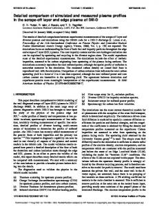
FIG. 3. Experimental x-ray images 共Ref. 11兲 of imploded capsule cores for the drive conditions of Fig. 2, viewed through a LEH. The initial design 共a兲 has a predicted average drive uniformity of 32⬃2% – 3%, causing a characteristic triangular core, while the optimized design 共b兲 produced a nearly round core with a drive uniformity of 32⬍1%. The three points in the triangular image are oriented toward the other three LEHs. Image 共a兲 was taken with a time-integrating pinhole camera and image 共b兲 with an x-ray framing camera.
FIG. 2. Predicted drive uniformity on the capsule in a tetrahedral hohlraum. The rms present in the dominant spherical harmonic mode Y 32 is plotted vs time for 共a兲 the initial scale-1 design for a 1 ns square pulse and 共b兲 the optimized scale-1.2 PS22 design. The amplitude of 32 gives the rms nonuniformity when all other modes are absent. The dashed curves were produced by the energy-balance model described in Sec. II, and the solid curves were calculated by the wall-diffusion model described in Sec. III.
where P gas is the internal gas pressure of the capsule, assuming adiabatic heating of the fuel. The radius of the shell r shell is measured in centimeters and the time t in seconds. This simple model has been found to predict remarkably accurate implosion trajectories, giving a stagnation time of 3 ns for PS22 in close agreement with experiment. Coupling the view-factor vacuum radiation transport with the time-varying capsule radius then gives a prediction for the time-dependent radiation-drive uniformity on the capsule. Figure 2 shows the spatial uniformity of the x-ray drive incident on the capsule as a function of time for two different tetrahedral designs. The dashed curves are the result of the radiation source as determined from Eqs. 共2兲 and 共3a兲 coupled to the 0-D rocket model. The time-dependent albedo used in Eqs. 共2兲 and 共3a兲 was obtained from the walldiffusion model described in Sec. III. The results of this diffusion model are shown as the solid curves. Since the nonuniformity is typically dominated 共⬎90%兲 by the Y 32 spherical-harmonic mode, we show only the contribution from 32 , where the total rms is defined as in Ref. 22: 2 rms ⬅
2 lm . 兺 l,m
共5兲
For both designs, Fig. 2 shows a noticeable improvement in drive uniformity later in time. This is primarily a consequence of the converging capsule radius. Note that the simple energy-balance calculation agrees quite well with the
more detailed wall-diffusion calculation throughout most of the laser pulse. At early times, the single-albedo assumption of the energy-balance model breaks down since the energy that should be confined to a few small laser-heated spots is spread over the entire hohlraum wall, predicting a more uniform drive. The effect of this early nonuniformity on target performance is not expected to be significant, however, since little energy irradiates the capsule at these times. Also, Eq. 共2兲 implies that, after the laser turns off, the radiation temperature 共and thus the drive nonuniformity兲 immediately goes to zero, while in reality the hohlraum wall acts as a heat reservoir, radiating stored energy well after the end of the laser pulse. This is important for the targets discussed in the following, where peak compression and neutron production occur several hundred picoseconds after the end of the laser pulse. The first experimental tetrahedral hohlraums 共shot on OMEGA in March 1997兲 were designed to have the same surface area and total LEH area as a standard cylindrical Nova hohlraum, thus giving comparable drive temperatures for the same laser pulse. This ‘‘scale-1’’ tetrahedral hohlraum had R case⫽1150 m and R LEH⫽450 m. The predicted radiation-drive uniformity of 2%–3% for a 1 ns flattop pulse was certainly good by most ICF standards,24,25 but the tetrahedral geometry on OMEGA was capable of much better uniformity. With the help of BUTTERCUP, the tetrahedral hohlraum was redesigned to give the best-possible drive uniformity while still maintaining reasonable radiation temperatures and sufficient clearance for the laser beams.26 The optimized design, known as a scale-1.2 hohlraum, had R case⫽1400 m, R LEH⫽350 m and different laser pointing parameters. The optimized design had a total LEH area of 1.54 mm2, a little less than the 2.26 mm2 of a standard Nova hohlraum. Additionally, the shaped laser pulse PS22 was used to achieve more efficient implosions and reduce laser– plasma instabilities in the hohlraum. Figures 2共a兲 and 2共b兲 correspond to the initial and optimized designs, respectively. The difference between a peak drive uniformity of 3% and one of 1% is apparent when comparing experimental images of the imploded cores, as shown in Fig. 3. The initial design, with 32⬃3% at the peak of the drive, results in a core with a clear triangular shape 关Fig. 3共a兲兴, corresponding
Downloaded 16 May 2005 to 130.58.92.250. Redistribution subject to AIP license or copyright, see http://pop.aip.org/pop/copyright.jsp
2968
Phys. Plasmas, Vol. 7, No. 7, July 2000
J. D. Schnittman and R. S. Craxton
to weaker drive pressure at the points on the capsule that directly face the LEHs. The resulting 3-D tetrahedron-shaped core looks like a triangle when viewed along the axis of one of its vertices 共through a LEH兲. With the optimized design, the imploded core is almost perfectly round 关Fig. 3共b兲兴, representing one of the most uniform indirect-drive implosions recorded to date. The optimized design for OMEGA benefits from a favorable ratio of the case radius to the capsule radius. The tradeoff is a lower coupling efficiency due to the ⬃40% extra wall area. However, the tetrahedral geometry on OMEGA has the advantage that all 60 beams can be used, compared with a maximum of 40 for cylindrical hohlraums. On the NIF, the tradeoff between uniformity and efficiency will be a key issue, especially for capsules with the larger convergence ratios that will be required.
FIG. 4. Schematic of the view-factor algorithm used by the code BUTTERCUP to calculate radiation transfer within the hohlraum. The x-ray flux incident at each point P on the wall is determined by integrating the visible brightness B e over a hemisphere of solid angle. The low-albedo capsule acts effectively as a shield, blocking the radiation transfer between opposite sections of the hohlraum wall.
III. RADIATION TRANSPORT AND DIFFUSION
The simple zero-dimensional model described in Sec. II works well for designing hohlraum targets and estimating the radiation-drive uniformity, but it has some significant shortcomings. For one, the assumption of a single, spatially independent albedo tends to break down early in the laser pulse, when the cold, unirradiated sections of the wall typically have a much lower albedo than the laser-heated spots.27,28 The energy-balance model also fails at later times, after the end of the laser pulse, giving a radiation temperature of zero. Additionally, the dependence on an external calculation or experimental measurement of the time-varying albedo limits BUTTERCUP’s ability to scan through a wide variety of pulse shapes and hohlraum designs. Finally, while the predicted time-dependent drive uniformity agrees qualitatively with experimental data, it unfortunately does not provide a means for quantitative comparison. To address these limitations, BUTTERCUP has been expanded to model the gold wall as a 2-D grid of mass elements, each with a different temperature profile and radiation brightness. Each point on this 2-D grid is treated as a separate problem in 1-D planar geometry, with the radiation transport into the wall modeled by solving an energy diffusion equation. The boundary zone of each 1-D section is driven by a radiation source from other portions of the hohlraum wall and, for the directly irradiated sections, a laser source. The deposited energy then propagates into the wall 共along x兲 according to the diffusion equation, assuming a single radiation and matter temperature T w (x,t) at each point in the wall. This treatment is similar to that of Tsakiris,27 except that he used 1-D self-similar solutions rather than individual 1-D calculations. Following Rosen29,30 we use the diffusion equation
冋
c R 共 aT w4 兲 共 ⑀ 兲⫽ t x 3 x
册
in the interior of the wall, and apply
共6a兲
共6b兲 to the boundary zone. Here ⑀ is the energy density of the wall material 共ergs/cm3兲, which scales as T w1.5 , the diffusion coefficient is 31 c R , and aT w4 关 a⫽4 /c 兴 is the radiant energy density. The Rosseland mean free path R is given as a function of temperature and density.29 The last term in Eq. 共6b兲 is the radiation flux seen by the point on the wall, integrated over all solid angles 共i.e., over all other boundary zones on the hohlraum wall兲. This term couples together all the individual 1-D diffusion calculations: Each boundary zone emits into the hohlraum cavity a flux T w4 (r) 共brightness T w4 (r)/ 兲, of which a large fraction provides a source for other boundary zones and a smaller fraction is lost to the capsule and LEHs. In Eq. 共6b兲, ⌬x is the thickness of the boundary zone, where the energy from the laser and radiation source terms is deposited. In the limit of ⌬x→0 the left-hand side of Eq. 共6b兲 tends to zero 共i.e., the boundary cell has negligible heat capacity兲 and Eq. 共6b兲 then acts as a boundary condition on T w4 / x for the diffusion equation. It is for this reason that the numerical solutions of Eq. 共6兲 are convergent 共i.e., independent of ⌬x兲 as ⌬x→0. In this limit, the laser source and the incident radiation from the other zones on the hohlraum wall balance the radiative loss into the hohlraum cavity and the diffusive loss into the hohlraum wall. The term 兰 T w4 (r)cos d⍀ is calculated in a way very similar to the view-factor integration used for determining the radiation incident on the capsule. Figure 4 shows a schematic representation of this algorithm, where the incident radiation intensity at a given point P on the hohlraum wall is determined by tracing rays over all solid angles and summing the relative brightness detected from each direction. Of
Downloaded 16 May 2005 to 130.58.92.250. Redistribution subject to AIP license or copyright, see http://pop.aip.org/pop/copyright.jsp
Phys. Plasmas, Vol. 7, No. 7, July 2000
Three-dimensional modeling of capsule implosions . . .
course, the LEHs do not contribute anything to the incoming radiation and the low-albedo capsule acts effectively as a shield, blocking the radiation transfer between opposite sections of the hohlraum wall. If there were no capsule present, the spherical geometry would provide perfect radiation uniformity incident on every point of the wall not directly heated by a laser source, regardless of the spatial emission distribution or the size of the LEHs, as long as the spectral brightness is independent of angle 共i.e., Lambertian兲 as is the case for blackbody radiation.27 This makes tetrahedral hohlraums particularly well suited for nonimplosion experiments that require a uniform x-ray source for driving foils or other packages mounted on the hohlraum wall. Here, as in Sec. II, the emitted wall brightness is taken to be T w4 (r)/ , independent of angle. This is probably a good assumption except at very early times when the steep gradient of T w within the wall 共see Fig. 5 below兲 results in different angles viewing different values of T w at about one optical depth into the wall. An angle-dependent brightness could be added to the model. It is instructive to compare Eq. 共6b兲 with Eq. 共3a兲, obtained for the simpler model of Sec. II. The radiation source term of Eq. 共6b兲 may be written as T R4 (r), defining an effective hohlraum temperature T R (r) as seen by a point r on the wall that is analogous to T r of Sec. II. Generally the spatial dependence of T R (r) is weak: as stated previously, T R (r) would be independent of r for a spherical hohlraum in the absence of a capsule. This provides justification for the use of a single T r in Sec. II to describe the radiation field in the cavity. It is also possible to define a local albedo ␣ 2 (r) ⬅1⫺  2 (r) by requiring  2 (r) T R4 (r) to equal 共⫺1兲 times the first term on the right-hand side of Eq. 共6b兲, i.e., the diffusive loss into the wall. With these definitions, the flux of x rays emitted into the hohlraum cavity becomes
T w4 ⫽ ␣ 2 共 r兲 T R4 共 r兲 ⫹ l I l 共 r兲 ,
共7兲
which compares closely with the right-hand side of Eq. 共3a兲. The first model can thus be expected to best match the second model if ␣ w is taken to be the average of ␣ 2 (r) over the hohlraum wall. An example of the nonlinear heat wave 共Marshak wave31兲 described by Eq. 共6兲 is shown in Fig. 5, for an unirradiated section of the gold wall. Here the wave is plotted at 100 ps intervals for an illustrative calculation in which a hohlraum is driven by a 1 ns square pulse. The penetration rate is commonly approximated as being proportional to 冑t, 29,31,32 although this approximation breaks down when blowoff and other effects are included.16,29 Even after the laser is turned off, the radiation continues to diffuse into the wall; however, much of the energy in the radiation field within the hohlraum cavity leaks out through the LEHs, lowering the temperature at the boundary surface. Note that it is not necessary to calculate the albedo explicitly in this model: the radiation emitted into the hohlraum from each boundary cell is given directly from the T w there as T w4 . With the temperature T w defined at each point on the hohlraum wall, it is straightforward to predict what the experimentally measured radiation temperature T r will be as a function of time. For the tetrahedral hohlraum experiments
2969
FIG. 5. Wall temperature T w as a function of distance into the gold wall, plotted at 100 ps intervals throughout a 1 ns square-pulse drive shot. For the duration of the laser pulse, the temperature at the boundary rises as the Marshak radiation wave propagates into the hohlraum wall; it then decreases as the wall cools after the laser is turned off.
on OMEGA, T r (t) was measured with the multichannel soft x-ray diagnostic Dante.33 This looked directly through one of the LEHs, viewing a combination of laser spots and unirradiated wall, representative of what the capsule should see, and thus eliminating the need for ‘‘albedo corrections.’’34 For a 22.0 kJ PS22 drive shot 共i.e., a shot without a capsule兲, the theoretical and experimental temperatures were in close agreement, as shown in Fig. 6.11 The data are from a scale1.2 tetrahedral hohlraum with 500 m radius LEHs 共larger than the 350 m LEHs used for the optimized implosions兲. For the BUTTERCUP calculation, the experimentally measured SBS 共stimulated Brillouin backscatter兲 fraction of 6% was taken out of the input laser energy. The close agreement with experiment indicates that the basic hohlraum energetics can be accurately modeled with BUTTERCUP’s relatively simple combination of diffusion and view-factor calculations. By this method of performing multiple 1-D diffusion calculations on a 2-D grid covering the hohlraum wall, and coupling them together through view-factor radiation transport, BUTTERCUP provides a 3-D description of the time-
FIG. 6. Hohlraum radiation temperature T r as a function of time for a 22.0 kJ PS22 drive experiment with 500 m radius LEHs. The LASNEX predictions 共dotted curve兲 and the experimental data 共solid curve兲 measured by the Dante multichannel, soft x-ray diagnostic are taken from Ref. 11. The dashed curve is the BUTTERCUP calculation, with the input laser power P las adjusted for the experimental SBS backscatter fraction of 6%.
Downloaded 16 May 2005 to 130.58.92.250. Redistribution subject to AIP license or copyright, see http://pop.aip.org/pop/copyright.jsp
2970
Phys. Plasmas, Vol. 7, No. 7, July 2000
dependent radiation uniformity on the capsule. This approach allows remarkably rapid simulations without sacrificing physical accuracy. Since fully 3-D radiationhydrodynamics codes typically take hundreds of CPU hours to do a single simulation on even the fastest supercomputers, pseudo-3D calculations like those presented in this paper will be increasingly valuable. The speed of BUTTERCUP also provides the ability to perform multiple simulations with different hohlraum parameters, making the code an ideal tool for developing new target designs. The evaluation of the effects on uniformity of pointing errors and beam imbalance provides a good example of the type of problem for which BUTTERCUP is ideally suited.35 With each point on the hohlraum wall being modeled independently, the computational overhead associated with changing the beam pointings and energies is very small, even though the tetrahedral symmetry is lost. One limitation of the model is the assumption of an idealized blackbody radiation spectrum. For example, it would not be correct to treat M-band radiation from multikiloelectron volt laser-heated plasma with Eq. 共6兲, which emits blackbody radiation into the hohlraum with the temperature of the dense wall plasma. Here, following Eq. 共3c兲, it would be reasonable to assume that half of this radiation is emitted into the hohlraum and half is lost in the wall 共with ␣ w⬘ ⫽0兲. The flux and uniformity of M-band radiation on the capsule could nevertheless be calculated with the model of Sec. II using ␣ w⬘ ⫽0 and taking l⬘ to give the observed emission of M-band radiation from the hohlraum wall. We conclude this section by demonstrating that the simple energy-balance model described in Sec. II provides a remarkably accurate description of the radiation temperature T r (t) when given a single, spatially averaged albedo as a function of time. This may be seen from Fig. 7, which plots T r (t) for 共a兲 the initial design 共1 ns square pulse兲 and 共b兲 the optimized design 共PS22 shaped pulse兲. The solid curves correspond to the more accurate wall-diffusion model and the dashed curves to the energy-balance model. Here we use the spatially averaged albedo 共dotted curves兲 calculated by the wall-diffusion model as input for the energy-balance model. For both cases the albedo rises rapidly to about 0.8. For the duration of the laser pulse, the two models agree very closely, suggesting a close equilibrium between the incident laser power and the radiation field. After the laser pulse ends, the albedo becomes greater than unity since the cooling wall emits more energy than it absorbs. This is also the point at which the energy-balance model breaks down completely, as the  w in Eq. 共2兲 becomes negative, the left-hand side of Eq. 共2兲 becomes zero, and the wall acts like a radiation source rather than a sink. IV. CAPSULE IMPLOSIONS
Given the 3-D, time-dependent radiation field incident on the capsule, BUTTERCUP also provides a pseudo-3D model of the actual hydrodynamic capsule implosion within a tetrahedral 共or cylindrical兲 hohlraum. For a given x-ray drive intensity I r ( , ,t) on the surface of the capsule, the incident radiation is treated as a blackbody spectrum and deposited
J. D. Schnittman and R. S. Craxton
FIG. 7. Hohlraum radiation temperature T r as a function of time for two implosion experiments: 共a兲 scale-1 hohlraum with a 30 kJ, 1 ns square pulse 共initial design兲; 共b兲 scale-1.2 hohlraum with a 24.6 kJ, PS22 shaped pulse 共optimized design兲. The wall-diffusion model produced the solid curves and a time-dependent, spatially averaged albedo, defined here as the total power radiated from the hohlraum wall divided by the total radiative power incident on the wall 共dotted curve兲; this albedo was then used as input in the energy-balance model to give the dashed curves.
into the plastic shell in multiple energy and angular groups. Like the pseudo-3D treatment of the gold wall, the capsule is modeled as a collection of 1-D calculations, each with its own radiation source term. However, unlike the treatment of the gold wall 共where just the Rosseland opacity is used兲, the radiation transport within the capsule plasma is modeled in greater detail using multigroup opacities.36 Each angular wedge of the capsule is modeled as a spherically symmetric problem with 1-D Lagrangian hydrodynamics. About 100 material zones are typically used in the radial direction, with roughly half in the shell and half in the fuel. The radiation energy from the hohlraum wall is deposited in the CH plasma using an S N algorithm, which divides the incident radiation into different angular groups,37 as is represented by Fig. 8. The x rays that are nearly normal to the surface penetrate deeper into the shell, while the higherangle x rays deposit the majority of their energy closer to the outside of the capsule. Since opacities are often quite sensitive to photon energy, the Planckian spectrum from the hohlraum wall is divided into multiple frequency groups, each containing a fraction of the blackbody radiation flux T r4 and each penetrating the plastic shell to a different depth. BUTTERCUP models the capsule implosion by solving the 1-D spherical Lagrangian hydrodynamic equations, including electron thermal diffusion and multigroup radiation diffusion within the capsule. The basic hydrodynamic equations in a spherically symmetric geometry are37
Downloaded 16 May 2005 to 130.58.92.250. Redistribution subject to AIP license or copyright, see http://pop.aip.org/pop/copyright.jsp
Phys. Plasmas, Vol. 7, No. 7, July 2000
Three-dimensional modeling of capsule implosions . . .
2971
FIG. 8. Multiple angular groups used to model radiation absorption in the capsule shell. X rays with small angles of incidence ␣ penetrate deeper into the ablating plasma, while higher-angle groups deposit their energy closer to the outside of the capsule.
r ⫽v, t v ⫽⫺4 r 2 共 P⫹Q 兲 , t m
共8兲
⑀ ⫽⫺4 共 r 2 v 兲关 P⫹Q 兴 , t m where P is the hydrodynamic fluid pressure, Q is the ‘‘artificial viscous stress,’’ r and v are the position and velocity of Lagrangian zone markers, and m is the differential mass element. For each step of the calculation, P and the specific energy ⑀ 共ergs/g兲 are determined from the SESAME equationof-state tables.38 The electron thermal diffusion is calculated using
共 ⑀ 兲 ⫽⫺“"Q e ⫽“"共 0 “T e 兲 , t
共9兲
where T e is the electron temperature, here assumed to be the same as the ion temperature T i , and 0 is the thermal diffusion coefficient, a function of the temperature, density, and ionization of the plasma. The multigroup radiation transport is modeled in two steps: first by angular S N absorption from the hohlraum wall and then with a mean-free-path diffusion approximation within the capsule. The absorption is determined39 by the opacity ⬘ corrected for stimulated emission 关 ⬘ ⫽ (1 ⫺e ⫺h /kT ) 兴 and the incident intensity I for each frequency group: dI ⫽⫺ ⬘ I , ds
共10兲
where s measures distance in the appropriate direction. Thus, in a region of constant opacity, I falls off exponentially. The internal diffusion equation, including emission and reabsorption, is
U ⫺“"共 D ⵜU 兲 ⫽c ⬘ 关 U P⫺U 兴 , t
共11兲
FIG. 9. 共a兲 Evolution of 1-D Lagrangian interface markers during a PS22 implosion with 50 atm of DD fuel inside a standard Nova capsule. The region of peak x-ray power absorption closely follows the steepest density gradient in the ablating shell for the duration of the laser pulse. The dashed curve shows the trajectory of a thin shell predicted by the 0-D rocket model. 共b兲 Velocity of the shock front propagating through the capsule as a function of time. The first shock breaks out from the shell into the DD fuel at 1.5 ns and converges on the origin at 2.6 ns, followed by the second shock convergence at 2.9 ns. Stagnation and bang time, the time at which the neutron production rate Y˙ peaks, occur at t⬃3 ns.
where U is the spectral radiation energy density 共ergs/cm3/unit frequency兲, U P is the Planckian radiation energy density for a given temperature, D is the frequencydependent diffusion constant (⫽c/3 ⬘ ), and c is the speed of light. BUTTERCUP uses opacity data from the Los Alamos Astrophysical Tables,36 which include opacities for values of h /kT between 0.001 25 and 30 000. For the small number of points outside this regime, the data are interpolated between the cold opacity and the closest known tabular opacity. As shown in Fig. 9共a兲, the peak x-ray power absorption during the laser pulse occurs in the shell near the steepest density gradient, unlike direct-drive implosions where the laser energy is deposited in the plasma corona and must be transported inward toward the ablation front. Even after the laser pulse ends, the hohlraum still provides significant radiation drive, penetrating deep into the ablating shell. Indirect-drive capsule implosions involve both radiative and shock heating in addition to the adiabatic heating and cooling of the plasma.40 The velocity of the shock front, defined as the point of maximum artificial viscous pressure, is shown as a function of time in Fig. 9共b兲, a negative value indicating convergence inward. The first shock is driven by the ⬃150 eV radiation temperature produced during the foot portion of the laser pulse. When it breaks out on the inside of the plastic shell, it experiences ‘‘velocity multiplication,’’ a general phenomenon that occurs whenever a shock wave
Downloaded 16 May 2005 to 130.58.92.250. Redistribution subject to AIP license or copyright, see http://pop.aip.org/pop/copyright.jsp
2972
Phys. Plasmas, Vol. 7, No. 7, July 2000
FIG. 10. Temperature and density profiles for the DD fuel and surrounding CH ablator in the capsule core at bang time 共3.0 ns兲, which closely corresponds to hydrodynamic stagnation. The fuel is assembled in a small, hot region of low-density gas surrounded by the colder, dense plastic pusher. The convergence ratio 共R i /R f for the CH–DD interface兲 for this PS22 implosion is about 10.
crosses a boundary from a denser material to a lighter material. Figure 9共b兲 shows that the shock speed jumps from 6 ⫻106 to 1.2⫻107 cm/s around t⫽1.4 ns. Then, as the radiation drive from the hohlraum increases near the peak of the laser pulse, the shell and fuel accelerate inward until 2.6 ns, when the first spherical shock wave converges at the origin and sends a reverse shock outward through the fuel. At 2.75 ns, this reflected shock meets the imploding plastic shell, which continues to converge until stagnation around 3.0 ns. The point of stagnation closely corresponds to the peak core temperature and also to the time of peak neutron production, referred to as the ‘‘bang time.’’ The density and temperature profiles of the core at bang time are shown in Fig. 10, plotted as functions of distance from the capsule center. The results shown are from a standard PS22 capsule implosion at t⫽3.0 ns, with the DD fuel assembled in a hot, central region surrounded by the cold, dense plastic shell. The radius of the fuel–pusher interface is R f ⫽23 m, giving a convergence ratio of C R⬃10. BUTTERCUP calculates the neutron yield from the D共D,n) 3 He reaction using Hively’s formulas for Maxwellian distributions.41 Since this reaction is so strongly dependent on temperature,42 almost the entire yield occurs during a short 共⬃200 ps兲 time when the fuel reaches its maximum temperature and density. Figure 11 shows this nuclear burn
FIG. 11. D共D,n) 3 He fusion yield as a function of time for a standard implosion driven with PS22. Also shown are the average fuel temperature and the radius of the fuel–pusher interface. The very strong temperature dependence of the fusion rate results in almost all neutron production occurring within about 200 ps.
J. D. Schnittman and R. S. Craxton
profile as a function of time for a standard PS22 implosion with a bang time of 3.0 ns. The ‘‘foot’’ of the neutron pulse corresponds to the second spherical shock converging at the origin, as shown in Fig. 9共b兲, which raises the average fuel temperature to 0.7 keV. This is followed by the peak compression and stagnation, when most of the neutrons are produced. After bang time, the core rapidly cools by thermal and radiative diffusion into the surrounding cold material, as well as through adiabatic expansion. The spherical uniformity of capsule implosions is frequently assessed by comparing the experimental fusion yields to those predicted by a purely one-dimensional calculation. Usually referred to as ‘‘yield over clean’’ 共YOC兲, this ratio provides an indication of how the capsule’s 3-D distortion affects the neutron yield and thus the success of the implosion.43,44 The cause of core distortion may be understood on a very simple level. Following Wallace,45 the implosion velocity scales as V imp⬀T r1.5⬀I r3/8 ,
共12兲
so for a peak-to-valley variation in drive uniformity of 10% 共typical for rms⫽2.5%兲, there should be a peak-to-valley difference of about 4% for the implosion velocity. For a convergence ratio of 10, this means that at the point of maximum compression, the core distortion—as measured by a/b, the ratio of major to minor axes—will be 1.56. For a peakto-valley difference of 2% in drive uniformity, however, the resulting core distortion will be only 1.07, or nearly round. For a high-convergence capsule with the same drive uniformity and C r ⫽30, a/b⫽1.28. While this model is conceptually helpful to understanding the relation between drive uniformity, convergence, and core distortion, we find that it generally overpredicts the values for a/b. This is probably because it omits the deceleration and stagnation caused by the gas pressure of the compressed fuel, as well as 3-D hydrodynamic smoothing effects that take place during the implosion, causing the relation in Eq. 共12兲 to break down. BUTTERCUP uses a pseudo-3D algorithm to model more accurately the effects of nonuniform drive on a capsule implosion and thus predict the core deformation as well as the neutron yield degradation. Just as the hohlraum wall is modeled in pseudo-3D by coupling a large number of 1-D calculations, the capsule is modeled by performing many 1-D spherical implosion calculations at the same time and coupling them together. As with earlier work that investigated deviations from uniform spherical implosions using a spherical-harmonic expansion,46 this approach is best suited to implosions that are close to spherically symmetric. To divide the capsule into multiple 1-D wedges of equal solid angle, we take advantage of the unique dodecahedral symmetry of the OMEGA target chamber. As mentioned previously, the 60 laser beams can be divided into 12 groups of 5 independent beams. Only these 5 beams need to be explicitly modeled in the hohlraum; the other 11 groups can be added by rotating the original group, greatly simplifying the 3-D problem. Similarly, the spherical capsule can be divided into 12 pentagonal wedges, all interchangeable through transformations in the dodecahedral rotational group. Figure 12 shows schematically how the sphere is di-
Downloaded 16 May 2005 to 130.58.92.250. Redistribution subject to AIP license or copyright, see http://pop.aip.org/pop/copyright.jsp
Phys. Plasmas, Vol. 7, No. 7, July 2000
Three-dimensional modeling of capsule implosions . . .
FIG. 12. Geometry used by BUTTERCUP to model a 3-D capsule implosion in a tetrahedral hohlraum on OMEGA. Using the natural dodecahedral symmetry, the spherical target is divided into 12 pentagonal-shaped wedges. Each wedge contains one-third of a LEH and five independent laser beams. This pentagonal wedge of the capsule is in turn divided into multiple triangular wedges of equal solid angle. Each triangular wedge is modeled with a single 1-D hydrodynamic calculation and is then coupled to neighboring wedges.
vided into pentagonal wedges, only one of which is actually modeled. This wedge corresponds to one group of five laser beams and a section of the hohlraum wall including one-third of a LEH. The pentagonal wedge of the capsule is then divided into triangular slices, each with the same solid angle and all converging at the same origin. For convenient division into symmetric wedges, 10, 30, or 90 triangular slices are typically used. All of these slices are modeled simultaneously with the spherical 1-D Lagrangian hydrodynamic model described previously. Each has a unique radiation-drive input, determined by the dynamic model of the hohlraum wall and the 3-D view-factor radiation transport. For most tetrahedral implosions, the radiation drive can be thought of as nearly uniform, with a small, time-dependent Y 32 perturbation. This will in turn cause a nearly spherical implosion, with Y 32 variations in the hydrodynamic variables throughout the capsule. This is very convenient since the spherical harmonic functions are solutions to the angular portion of the diffusion equation in a spherical geometry:47
f 共 r, , ,t 兲 ⫽“"D 共 r 兲 “ f 共 r, , ,t 兲 . t
共13兲
For short times ⌬t, over which the diffusion constant D(r) can be treated as static, solutions are eigenfunctions of the form f 共 r, , ,⌬t 兲 ⫽R 共 r,⌬t 兲 U r 共 , ,⌬t 兲 , where U r 共 , ,⌬t 兲 ⫽
冋
c lm Y lm 共 , 兲 exp 兺 l,m
共14兲
册
⫺l 共 l⫹1 兲 D 共 r 兲 ⌬t r2 共15兲
and R(r,⌬t) is calculated with the 1-D spherical hydrodynamics of Eqs. 共8兲–共11兲. In BUTTERCUP, f (r, , ,t) represents either the electron temperature or the energy density of a radiation group, and Eq. 共15兲 is used to calculate its evolution over short periods of time ⌬t. For tetrahedral hohlraums on OMEGA, only the Y lm ( , ) spherical-harmonic functions with dodecahedral symmetry will have nonzero coefficients in the sum. Just as the Y 32 moment dominates the
2973
radiation incident on the capsule, it is also the primary term in the angular diffusion equation and typically the only term explicitly calculated. For the angular portion of each 3-D diffusion step, the Lagrangian hydrodynamic variables are projected onto an orthogonal, Eulerian-type grid. This allows BUTTERCUP to solve Eq. 共15兲 for each concentric spherical shell of material, as opposed to lateral diffusion between Lagrangian zones with the same radial index that may be located at different physical radii. After the angular diffusion calculation, the new values of the temperature are projected back onto the pseudo-3D Lagrangian grid. This alternates with the separate 1-D hydrodynamic calculations 共including diffusion in the r direction兲 that change the values of R(r) and D(r) for each angular zone, which are then used as input for the next iteration of the 3-D diffusion calculation. In this way, the triangular slices of the capsule are coupled to produce a pseudo-3D implosion simulation. Since this algorithm does not include lateral mass transport, it cannot model more complicated 3-D phenomena like shock dispersion and hydrodynamic instabilities. Furthermore, since the converging radiation shock wave is not perfectly spherical, there can be sharp discontinuities in the hydrodynamic variables as the wave front propagates through the material. At a given radius near the shock front, some material may be cold and uncompressed, while the material in a neighboring zone may have been heated and compressed by the shock. At this point, the assumption of a smooth Y 32 perturbation in the temperature breaks down; however, for the tetrahedral hohlraum implosions performed on OMEGA, we find that this pseudo-3D model provides reasonable predictions for experimental observations. Specifically, BUTTERCUP was used to model a set of recent experiments on the OMEGA laser that utilized tetrahedral hohlraums to achieve high-convergence implosions.48,49 Indirect-drive capsules with convergence ratios as high as 20–30 have been shot previously on Nova43 and OMEGA50 in cylindrical geometry, typically giving YOC measurements of 5%–25%. By using the improved drive uniformity available with tetrahedral hohlraums, it was hoped to eliminate the effects of low-order nonuniformity on the fusion-yield degradation. For the first series of high-convergence tetrahedral experiments conducted in September 1998 and reported in Refs. 48 and 49, convergence ratios of about 10–20 were achieved, with values of YOC similar to earlier results using cylindrical targets with the same convergence. The highconvergence capsules were designed by varying the initial DD fill pressure, with lower-pressure capsules giving higher convergence. The experiment used 550-m-diam capsules with 55 m CH shells filled with 50, 25, and 8 atm of DD gas, corresponding to theoretical convergence ratios of 9, 11, and 16, respectively. They were driven with all 60 OMEGA beams with pulse shape PS22, delivering 21–25 kJ of UV light into the hohlraum. Figure 13共a兲 shows how the predicted neutron yields and convergence ratios depend on the DD fill pressure. Lowpressure capsules not only converge to a smaller radius, but they also reach higher core temperatures, leading to higher fusion yields even with significantly less fuel. BUTTERCUP’s
Downloaded 16 May 2005 to 130.58.92.250. Redistribution subject to AIP license or copyright, see http://pop.aip.org/pop/copyright.jsp
2974
Phys. Plasmas, Vol. 7, No. 7, July 2000
J. D. Schnittman and R. S. Craxton
creasing their adiabat and making an efficient implosion more difficult to achieve. The higher-convergence capsules (C R ⬃20) had the higher 1-D temperature predictions (T i ⫽1650 eV) but also experienced a greater reduction in core temperature due to 3-D effects 共⬍70% of 1-D temperature兲, which is clearly reflected in the degraded yield predictions 共YOC⫽17%兲. The preliminary experimental data of Fig. 13共b兲 seem to exhibit a more rapid falloff with convergence ratio than the BUTTERCUP calculations, although a larger data set is needed to quantify this. It appears that BUTTERCUP can explain only some of the YOC reduction at higher C R . The comparison suggests that, even with the best drive uniformity, hohlraum capsules are still susceptible to asymmetric shock convergence and other 3-D effects like Rayleigh–Taylor instabilities associated with physical defects caused during target manufacturing. Future experiments will hopefully help to identify the relative importance of irradiation nonuniformity and hydrodynamic instabilities. FIG. 13. 共a兲 Predicted 1-D and pseudo-3D yields and convergence ratio as a function of DD fuel pressure; 共b兲 3-D yield degradation 共solid line兲 as a function of calculated convergence ratio, along with experimental measurements of these yields 共Ref. 49兲. The theoretical yield degradation accounts only for effects caused by drive nonuniformity and not hydrodynamic instabilities. The experimental YOC values were based on experimental yields and 1-D BUTTERCUP predictions.
yield predictions with 3-D effects included are also shown. As expected, for higher-convergence implosions, the predicted 3-D yields are lower with greater degradation from the 1-D prediction. Figure 13共b兲 shows a plot of YOC versus convergence ratio, including both experimental49 and predicted YOC. A quantitative summary of the predicted results is presented in Table I. We believe that the major mechanism for yield degradation in the pseudo-3D model is the thermal transport of energy away from the area of the fuel that is heated earliest in the implosion. As in the 1-D simulation, the fuel temperature increases significantly as the first and second shock waves converge on the origin, but with the 3-D simulation, this occurs at different times for different fuel wedges. As soon as the strongly driven regions of the capsule heat up, they transfer their thermal energy to cooler neighboring zones. Not only does this reduce the yield of the hotter zones, but it also reduces the potential yield of the cooler zones by in-
V. X-RAY POSTPROCESSOR
One of the traditional ways11,44,51–53 to assess hohlraum drive uniformity is simply to implode a capsule and look at the shape of the core: round indicates good uniformity and elliptical 共in a cylindrical hohlraum兲 or triangular 共in a tetrahedral hohlraum兲 indicates poor uniformity. Experimentally, this can be done with a time-resolved x-ray-framing camera or with a time-integrated pinhole camera at high magnification. A pinhole camera with filtering chosen to absorb soft x rays automatically selects the bang-time image since the x-ray film detects mainly the high-intensity emission from the hottest part of the capsule. Since the fuel is usually so much hotter than the surrounding plastic shell, the actual shape of the fuel core tends to be well highlighted. In some instances, in order to improve the x-ray imaging, a small amount of high-Z gas such as argon or neon is added to the fuel, emitting higher-energy x rays at the same temperature. A thin film of beryllium is typically used as a filter on either camera to block out the low-energy radiation 共ⱗ2 keV兲 coming from the pusher region. BUTTERCUP creates an image of the imploded core by analyzing the results of its hydrodynamic calculation with a 3-D radiation postprocessor. The first step is to reconstruct the entire capsule by copying and rotating the single pentagonal wedge modeled by BUTTERCUP 11 times, piecing to-
TABLE I. Summary of BUTTERCUP 1-D and 3-D predictions for the convergence ratio (C R ), neutron yield 共Y兲, peak temperature 共T兲, peak areal density ( R), core distortion (a/b), and yield-over-clean 共YOC兲 ratio for capsule implosions driven by a PS22 laser pulse. Predictions of C R and peak R are similar for 1-D or 3-D calculations. DD fill 共atm兲
CR
Y (3-D) (108 )
Y (1-D) (108 )
Peak T 共3-D兲 共eV兲
Peak T 共1-D兲 共eV兲
Peak R 共mg/cm2兲
a/b
YOC 共theory兲
4 8 15 25 50
20.5 16.2 13.0 11.0 9.0
0.64 1.1 1.5 1.6 1.1
3.7 5.1 5.2 4.2 2.1
1125 1150 1075 1000 825
1650 1525 1350 1175 900
5.8 7.1 8.7 10.0 12.6
1.20 1.14 1.12 1.11 1.06
17% 21% 28% 37% 51%
Downloaded 16 May 2005 to 130.58.92.250. Redistribution subject to AIP license or copyright, see http://pop.aip.org/pop/copyright.jsp
Phys. Plasmas, Vol. 7, No. 7, July 2000
Three-dimensional modeling of capsule implosions . . .
FIG. 14. Algorithm for simulating experimental x-ray images. A multigroup x-ray postprocessor solves the radiation transport equation along rays traced through the 3-D Lagrangian grid of the capsule. A 5 mil 共127-m兲 beryllium filter is used to remove low-energy signals coming from the colder plastic shell, giving a view of only the hot central fuel region.
gether the 12 sections of a dodecahedron. This produces a complete three-dimensional model of the capsule, which is then rotated to give the correct orientation with respect to the x-ray camera. The complicated 3-D Lagrangian mesh can be projected onto a 2-D image by ray-tracing a grid of parallel lines through the 3-D capsule. Along the path of each ray, BUTTERCUP solves the multigroup radiation-transport equation,39 which is similar to Eq. 共10兲, except now with an additional source term I P, the blackbody intensity 共erg/s/cm2/unit frequency兲: dI ⫽ ⬘ 共 I P⫺I 兲 . ds
共16兲
Figure 14 shows a schematic of this procedure, including the Be filter and the x-ray film. The complicated 3-D mesh portrayed in this picture was constructed by connecting the centers of all adjacent Lagrangian zones, where each individual zone has the shape of a triangular prism. Upon exiting the capsule, each ray on the 2-D grid will have its own x-ray intensity spectrum over the range of relevant frequency groups. This spectrum is in turn filtered by the beryllium 共using cold opacities at solid density兲 and then integrated to give a single intensity point on the x-ray film. The resulting postprocessed image can then be directly compared with experimental data, either time averaged or time resolved. Figure 15 shows the simulated x-ray image of a standard PS22 implosion at bang time. Qualitatively this image is very similar to the experimental image of Fig. 3共b兲: both appear round to within experimental error. It should be noted that the formation of this projected image provides an apparent smoothing of the actual 3-D distortion. For this image the calculated ‘‘a/b ratio,’’ defined as the maximum-tominimum ratio of the radii of the 50%-intensity contour, is 1.02, while the a/b ratio of the fuel–pusher interface is 1.06. The reduction from 1.06 to 1.02 could be caused by geometric projection effects or by the nonuniform temperature distribution within the fuel, with the ‘‘corners’’ of the tetrahedral-shaped core being colder and thus not emitting as strongly.
2975
FIG. 15. A postprocessed simulation of the x-ray image of the imploded core corresponding to Fig. 3共b兲, integrated over a 200 ps window around bang time. The a/b ratio of major to minor axes 共1.02兲 is measured from the 50% contour of absolute x-ray intensity.
VI. CONCLUSIONS
Tetrahedral hohlraums have been proposed as an alternative approach to ignition in indirect-drive ICF. Recent experiments on the OMEGA laser have confirmed the predicted radiation drive uniformity ( rms⬍1%) incident on an imploding capsule. To further understand these implosions, the view-factor code BUTTERCUP has been expanded to include a 3-D, time-dependent treatment of the radiation diffusion into the gold wall and the radiation transport in the hohlraum. BUTTERCUP models the hydrodynamic implosion of the capsule by dividing it into many triangular wedges of equal solid angle, each undergoing a 1-D implosion driven by a different incident radiation source. These individual calculations are coupled together with 3-D thermal and radiation diffusion. Finally, an x-ray postprocessor is used to simulate an image of the imploded core. The wall-diffusion model predicts a time-dependent radiation-drive temperature that agrees closely with experimental measurements from Dante. Additionally, BUTTERCUP is able to calculate a time-dependent albedo, which in turn can be used in a simple energy-balance equation to estimate radiation-drive temperatures. The hydrodynamic implosion calculations have provided valuable insight into the physics of indirect-drive ICF capsule implosions. Given the simplicity of the implosion model, predicted bang times as well as nuclear fusion yields are in reasonable agreement with those seen in the experiments. Pseudo-3D calculations suggest that for high-convergence implosions, one potential cause of yield degradation is the asymmetric shock convergence since the fuel is not heated as efficiently as in a perfectly spherical implosion. The 3-D x-ray postprocessor has shown that experimental images of the imploded capsule underestimate the actual level of core distortion. These results show that, despite its relative simplicity, BUTTERCUP has already provided some critical new understanding of the connection between theory and experiment in hohlraum implosions. Finally, the pseudo-3D methods described in this paper will likely be useful for developing and testing the more sophisticated, fully three-dimensional codes
Downloaded 16 May 2005 to 130.58.92.250. Redistribution subject to AIP license or copyright, see http://pop.aip.org/pop/copyright.jsp
2976
Phys. Plasmas, Vol. 7, No. 7, July 2000
that are needed to provide detailed modeling of ignition hohlraums on the NIF.
ACKNOWLEDGMENTS
The authors gratefully acknowledge many valuable discussions with Dr. S. M. Pollaine and Dr. J. M. Wallace. They would also like to thank the referee for a very thorough review and many helpful suggestions. This work was supported by the U.S. Department of Energy Office of Inertial Confinement Fusion under Cooperative Agreement No. DEFC03-92SF19460, the University of Rochester, and New York State Energy Research and Development Authority. The support of DOE does not constitute an endorsement by DOE of the views expressed in this article.
J. Nuckolls, L. Wood, A. Thiessen, and G. Zimmerman, Nature 共London兲 239, 139 共1972兲. 2 J. D. Lindl, Phys. Plasmas 2, 3933 共1995兲. 3 S. E. Bodner, Comments Plasma Phys. Control. Fusion 16, 351 共1995兲. 4 S. W. Haan, S. M. Pollaine, J. D. Lindl, L. J. Suter, R. L. Berger, L. V. Powers, W. E. Alley, P. A. Amendt, J. A. Futterman, W. K. Levedahl, M. D. Rosen, D. P. Rowley, R. A. Sacks, A. I. Shestakov, G. L. Strobel, M. Tabak, S. V. Weber, G. B. Zimmerman, W. J. Krauser, D. C. Wilson, S. V. Coggeshall, D. B. Harris, N. M. Hoffman, and B. H. Wilde, Phys. Plasmas 2, 2480 共1995兲. 5 M. M. Marinak, R. E. Tipton, O. L. Landen, T. J. Murphy, P. Amendt, S. W. Haan, S. P. Hatchett, C. J. Keane, R. McEachern, and R. J. Wallace, Phys. Plasmas 3, 2070 共1996兲. 6 T. R. Dittrich, S. W. Haan, M. M. Marinak, S. M. Pollaine, and R. McEachern, Phys. Plasmas 5, 3708 共1998兲. 7 K. A. Brueckner and S. Jorna, Rev. Mod. Phys. 46, 325 共1974兲. 8 D. W. Phillion and S. M. Pollaine, Phys. Plasmas 1, 2963 共1994兲. 9 J. D. Schnittman and R. S. Craxton, Phys. Plasmas 3, 3786 共1996兲. 10 T. R. Boehly, D. L. Brown, R. S. Craxton, R. L. Keck, J. P. Knauer, J. H. Kelly, T. J. Kessler, S. A. Kupman, S. J. Loucks, S. A. Letzring, F. J. Marshall, R. L. McCrory, S. F. B. Morse, W. Seka, J. M. Soures, and C. P. Verdon, Opt. Commun. 133, 495 共1997兲. 11 J. M. Wallace, T. J. Murphy, N. D. Delamater, K. A. Klare, J. A. Oertel, G. R. Magelssen, E. L. Lindman, A. A. Hauer, P. Gobby, J. D. Schnittman, R. S. Craxton, W. Seka, R. Kremens, D. Bradley, S. M. Pollaine, R. E. Turner, O. L. Landen, D. Drake, and J. J. MacFarlane, Phys. Rev. Lett. 82, 3807 共1999兲. 12 H. Honda, H. Nishimura, S. Miyamoto, D. Ohnuki, K. Fujita, Y. Ochi, H. Miki, H. Takabe, S. Nakai, and K. Mima, Plasma Phys. Controlled Fusion 40, 1097 共1998兲. 13 S. M. Pollaine and D. Eimerl, Nucl. Fusion 38, 1523 共1998兲. 14 J. A. Harte, W. E. Alley, D. S. Bailey, J. L. Eddleman, and G. B. Zimmerman, ‘‘LASNEX—A 2-D Physics Code for Modeling ICF,’’ UCRL-LR105821-96-4 共1996兲. Copies may be ordered from the National Technical Information Service, Springfield, VA 22161. 15 R. L. Kauffman, L. J. Suter, C. B. Darrow, J. D. Kilkenny, H. N. Kornblum, D. S. Montgomery, D. W. Phillion, M. D. Rosen, A. R. Theissen, R. J. Wallace, and F. Ze, Phys. Rev. Lett. 73, 2320 共1994兲. 16 M. D. Rosen, Phys. Plasmas 3, 1803 共1996兲. 17 S. H. Glenzer, L. J. Suter, R. E. Turner, B. J. MacGowan, K. G. Estabrook, M. A. Blain, S. N. Dixit, B. A. Hammel, R. L. Kauffman, R. K. Kirkwood, O. L. Landen, M. C. Monteil, J. D. Moody, T. J. Orzechowski, D. M. Pennington, G. F. Stone, and T. L. Weiland, Phys. Rev. Lett. 80, 2845 共1998兲. 18 L. J. Suter, R. L. Kauffman, C. B. Darrow, A. A. Hauer, H. Kornblum, O. L. Landen, T. J. Orzechowski, D. W. Phillion, J. L. Porter, L. V. Powers, A. Richard, M. D. Rosen, A. R. Thiessen, and R. Wallace, Phys. Plasmas 3, 2057 共1996兲. 19 T. Mochizuki, S. Sakabe, and C. Yamanaka, Jpn. J. Appl. Phys., Part 2 22, L124 共1983兲. 20 A. Caruso and C. Strangio, Jpn. J. Appl. Phys., Part 1 30, 1095 共1991兲. 21 M. Murakami and J. Meyer-Ter-Vehn, Nucl. Fusion 31, 1333 共1991兲. 1
J. D. Schnittman and R. S. Craxton M. Murakami, Nucl. Fusion 32, 1715 共1992兲. K. H. Kang, K.-J. Lutz, N. A. Tahir, and J. A. Maruhn, Nucl. Fusion 33, 17 共1993兲. 24 P. Amendt, S. G. Glendinning, B. A. Hammel, O. Landen, and L. J. Suter, Phys. Rev. Lett. 77, 3815 共1996兲. 25 P. Amendt, T. J. Murphy, and S. P. Hatchett, Phys. Plasmas 3, 4166 共1996兲. 26 The significant contributions of K. A. Klare and D. Drake to the design are acknowledged. 27 G. D. Tsakiris, Phys. Fluids B 4, 992 共1992兲. 28 C. Sto¨ckl and G. D. Tsakiris, Phys. Rev. Lett. 70, 943 共1993兲. 29 See National Technical Information Service Document No. DE96000344 共Lawrence Livermore National Laboratory, Livermore, CA, Report UCRL-JC-121585 by M. D. Rosen, 1995兲. Copies may be ordered from the National Technical Information Service, Springfield, VA 22161. 30 M. D. Rosen, Phys. Plasmas 6, 1690 共1999兲. 31 R. E. Marshak, Phys. Fluids 1, 24 共1958兲. 32 R. Sigel, K. Eidmann, F. Lavarenne, and R. F. Schmalz, Phys. Fluids B 2, 199 共1990兲. 33 H. N. Kornblum, R. L. Kauffman, and J. A. Smith, Rev. Sci. Instrum. 57, 2179 共1986兲. 34 C. Decker, R. E. Turner, O. L. Landen, L. J. Suter, P. Amendt, H. N. Kornblum, B. A. Hammel, T. J. Murphy, J. Wallace, N. D. Delamater, P. Gobby, A. A. Hauer, G. R. Magelssen, J. A. Oertel, J. Knauer, F. J. Marshall, D. Bradley, W. Seka, and J. M. Soures, Phys. Rev. Lett. 79, 1491 共1997兲. 35 R. S. Craxton, J. D. Schnittman, and S. M. Pollaine, Bull. Am. Phys. Soc. 41, 1421 共1996兲. 36 See National Technical Information Service Document No. LA-6760-M/ XAB 共Los Alamos National Laboratory Report LA-6760-M by W. F. Huebner, A. L. Merts, N. H. Magee, Jr., and M. F. Argo, 1977兲. Copies may be ordered from the National Technical Information Service, Springfield, VA 22161. 37 R. L. Bowers and J. R. Wilson, Numerical Modeling in Applied Physics and Astrophysics 共Jones and Bartlett, Boston, 1991兲. 38 See National Technical Information Service Document No. LA-7130/ XAB 共Los Alamos National Laboratory Report LA-7130 by B. I. Bennett, J. D. Johnson, G. I. Kerley, and G. T. Rood, 1978兲. Copies may be ordered from the National Technical Information Service, Springfield, VA 22161. 39 Ya. B. Zel’dovich and Yu. P. Raiser, Physics of Shock Waves and HighTemperature Hydrodynamic Phenomena 共Academic, New York, 1966兲. 40 T. R. Dittrich, S. W. Haan, M. M. Marinak, S. M. Pollaine, D. E. Hinkel, D. H. Munro, C. P. Verdon, G. L. Strobel, R. McEachern, R. C. Cook, C. C. Roberts, D. C. Wilson, P. A. Bradley, L. R. Forcman, and W. S. Varnum, Phys. Plasmas 6, 2164 共1999兲. 41 L. M. Hively, Nucl. Fusion 17, 873 共1977兲. 42 B. N. Kozlov, At. Energ. 12, 247 共1962兲. 43 M. D. Cable, S. P. Hatchett, J. A. Caird, J. D. Kilkenny, H. N. Kornblum, S. M. Lane, C. Laumann, R. A. Lerche, T. J. Murphy, J. Murray, M. B. Nelson, D. W. Phillion, H. Powell, and D. B. Ress, Phys. Rev. Lett. 73, 2316 共1994兲. 44 T. J. Murphy, J. M. Wallace, N. D. Delamater, C. W. Barnes, P. Gobby, A. A. Hauer, E. L. Lindman, G. Magelssen, J. B. Moore, J. A. Oertel, R. Watt, O. L. Landen, P. Amendt, M. Cable, C. Decker, B. A. Hammel, J. A. Koch, L. J. Suter, R. E. Turner, R. J. Wallace, F. J. Marshall, D. Bradley, R. S. Craxton, R. Keck, J. P. Knauer, R. Kremens, and J. D. Schnittman, Phys. Plasmas 5, 1960 共1998兲. 45 J. M. Wallace, K. A. Klare, T. J. Murphy, N. D. Delamater, E. L. Lindman, G. R. Magelssen, A. A. Hauer, S. M. Pollaine, R. E. Turner, R. S. Craxton, and J. D. Schnittman, Bull. Am. Phys. Soc. 42, 2009 共1997兲. 46 R. L. McCrory, R. L. Morse, and K. A. Taggart, Nucl. Sci. Eng. 64, 163 共1977兲. 47 G. Arfken, Mathematical Methods for Physicists 共Academic, Orlando, 1985兲, p. 450. 48 J. M. Wallace, G. R. Bennett, T. J. Murphy, J. A. Oertel, P. Gobby, A. A. Hauer, W. S. Varnum, D. C. Wilson, R. S. Craxton, J. D. Schnittman, and S. M. Pollaine, Bull. Am. Phys. Soc. 43, 1737 共1998兲; J. D. Schnittman, R. S. Craxton, S. M. Pollaine, R. E. Turner, J. M. Wallace, T. J. Murphy, N. D. Delamater, J. A. Oertel, A. A. Hauer, and K. A. Klare, ibid. 43, 1737 共1998兲. 49 G. R. Bennett, J. M. Wallace, T. J. Murphy, A. A. Hauer, J. A. Oertel, D. C. Wilson, P. L. Gobby, N. D. Delamater, R. E. Chrien, R. S. Craxton, and J. D. Schnittman, Bull. Am. Phys. Soc. 43, 1737 共1998兲. 50 P. Amendt, R. E. Turner, O. Landen, S. G. Glendinning, D. Kalantar, M. 22 23
Downloaded 16 May 2005 to 130.58.92.250. Redistribution subject to AIP license or copyright, see http://pop.aip.org/pop/copyright.jsp
Phys. Plasmas, Vol. 7, No. 7, July 2000
Cable, J. Colvin, C. Decker, L. Suter, R. Wallace, D. Bradley, S. Morse, G. Picn, W. Seka, and J. M. Soures, Bull. Am. Phys. Soc. 43, 1739 共1998兲. 51 A. Hauer, N. Delamater, D. Ress, W. Hsing, L. Suter, L. Powers, O. Landen, D. Harris, R. Thiessen, G. Magelssen, E. Lindman, D. Phillion, P. Amendt, R. Watt, and B. Hammel, Rev. Sci. Instrum. 66, 672 共1995兲. 52 A. A. Hauer, L. Suter, N. Delamater, D. Ress, L. Powers, G. Magelssen, D. Harris, O. Landen, E. Lindmann, W. Hsing, D. Wilson, P. Amendt, R. Thiessen, R. Kopp, D. Phillion, B. Hammel, D. Baker, J. Wallace, R.
Three-dimensional modeling of capsule implosions . . .
2977
Turner, M. Cray, R. Watt, J. Kilkenny, and J. Mack, Phys. Plasmas 2, 2488 共1995兲. 53 T. J. Murphy, J. M. Wallace, N. D. Delamater, C. W. Barnes, P. Gobby, A. A. Hauer, E. Lindman, G. Magelssen, J. B. Moore, J. A. Oertel, R. Watt, O. L. Landen, P. Amendt, M. Cable, C. Decker, B. A. Hammel, J. A. Koch, L. J. Suter, R. E. Turner, R. J. Wallace, F. J. Marshall, D. Bradley, R. S. Craxton, R. Keck, J. P. Knauer, R. Kremens, and J. D. Schnittman, Phys. Rev. Lett. 81, 108 共1998兲.
Downloaded 16 May 2005 to 130.58.92.250. Redistribution subject to AIP license or copyright, see http://pop.aip.org/pop/copyright.jsp