PHYSICS OF PLASMAS
VOLUME 8, NUMBER 4
APRIL 2001
Establishment of strong velocity shear and plasma density profile modification with associated low frequency fluctuations Shunjiro Shinohara,a) Norikazu Matsuoka, and Shoichiro Matsuyama Interdisciplinary Graduate School of Engineering Sciences, Kyushu University, Kasuga, Fukuoka 816-8580, Japan
共Received 31 August 2000; accepted 27 December 2000兲 Strong shear of azimuthal plasma rotation velocity and a large density profile modification from a hollow to peaked profiles were successfully obtained in a cylindrical magnetized plasma, using voltage biased electrodes. The shear region and density profiles could be finely controlled by changing the voltage biased position as well as by the magnetic field configurations. A low frequency 共⬍4 kHz兲 density oscillation was identified as a drift wave type: propagation in the electron diamagnetic direction with a rigid rotation 共Mach number M ⬃⫺1 at the edge兲, opposite to the direction of the edge plasma rotation with M ⬃1. © 2001 American Institute of Physics. 关DOI: 10.1063/1.1350663兴
I. INTRODUCTION
manner from a basic viewpoint. This topic is expected to become a critical issue in the various fields mentioned previously. In this paper, we demonstrate for the first time the control of large profile change of the azimuthal rotation velocity in a supersonic regime 共Mach number M, defined as the plasma flow velocity normalized by the ion sound velocity C s , was greater than unity兲 with a strong shear, i.e., high vorticity, in addition to the density control from a hollow to peaked profiles. Using ten-separated voltage biased electrodes, under various magnetic field configurations, the plasma rotation and density profiles were finely varied with the associated low frequency fluctuations 共fundamental frequency ⬍4 kHz兲 propagated in the opposite direction of the edge plasma rotation. To our knowledge, novel control of this high M with a strong shear, not temporally, and of large density profile change have not been attempted previously. These results will contribute to many plasma application fields 共e.g., plasma source and an isotope separation兲, as well as to the profound understanding of the characteristics of plasma fluids and stabilities.
Fluid flow 共hydrodynamic兲 has been investigated to supply many physically interesting understandings so far, and plasma flow 共magnetohydrodynamic兲, including a rotational flow with associated instabilities 共nonlinear selforganizing phenomena兲, has been attracting many researchers in various fields, such as space plasma,2 nuclear fusion related to the enhanced magnetic confinement 共bifurcation兲 with the shear of so-called EÃB rotation 共E: electric field, B: magnetic field兲,3 and application fields 共isotope separation,4 propulsion in space,5 plasma processing,6 environment,7 etc.兲. These plasmas often exhibit inherent, similar, and universal characteristics in spite of the different parameter regimes. As for rotating plasmas in the basic field with an axial magnetic field, historically, studies on instabilities brought about by changing the E profile leading to the velocity shear were done using Q-machines.8,9 Also the instabilities were investigated in a non-neutral plasma.10 It is important to understand the formation mechanism of the transverse component of E, so that the desired EÃB azimuthal rotation3 can be induced. The pulsing of the electrostatic potential was first observed to change the transport.11 The parallel component of E is also interesting,12 e.g., as a double layer13 related to particle acceleration in the aurora phenomena and a thermal barrier in a tandem mirror.12,14 Recently, probe biasing 共voltage兲 has been attempted in order to modify the potential profile in a tokamak15 in terms of the enhanced plasma confinement, partly due to the change of EÃB velocity shear. In mirror-based devices, there is an increasing interest in the stabilization of low-frequency instabilities, such as flute and drift modes, and an interest in the wave excitation with a strong shear.16–21 However, in contrast to this active research, there have been few experiments22,23 to show a large change of the density profile with high azimuthal rotation velocity, which is connected with transport, in a controlled 1
II. EXPERIMENTAL SETUP
The experimental system used is shown in Fig. 1.23,24 Argon plasma was produced by a four-turn spiral antenna at a pressure of P⫽0.1– 0.2 mTorr. Continuous output rf power and frequency of 400–500 W and 7 MHz, respectively, were applied to a linear device, 45 cm in diameter and 170 cm in axial length. Three magnetic field configurations were tested: uniform field 共case A, magnetic field strength B⫽500 G兲, good 共case B, B⫽360– 700 G兲, and bad 共case C: mirror field, B⫽220– 550 G兲 field curvatures. The plasma parameters were measured by Langmuir probes, including a Mach probe, which is a directional probe, for the plasma flow measurements. The typical target 共before biasing兲 plasma density n e was in the range of 4⫻109 – 2 ⫻1010 cm⫺3 with electron temperature T e ⫽3 – 6 eV and estimated ion temperature ⬍1 eV 共ion Larmor radius i
a兲
Electronic mail:
[email protected]
1070-664X/2001/8(4)/1154/5/$18.00
1154
© 2001 American Institute of Physics
Downloaded 17 Apr 2001 to 133.5.186.8. Redistribution subject to AIP copyright, see http://ojps.aip.org/pop/popcr.jsp
Phys. Plasmas, Vol. 8, No. 4, April 2001
Establishment of strong velocity shear . . .
1155
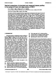
FIG. 2. Radial profiles of ion saturation current, I is , changing a position of biased electrode 共case A: biased voltage V b ⫽150 V兲. Radial positions of the electrodes are also shown for reference.
FIG. 1. Schematic view of 共a兲 experimental setup and 共b兲 biased electrodes with ten concentric rings.
⬍1 cm兲. In order to control the radial potential profile, we used ten concentric, segmented rings23 with thickness of 0.03 cm 共in the axial direction兲 as biased electrodes 关see Fig. 1共b兲兴. The inner and outer diameters of the nth ring 共in order from the center兲 were 4n⫺4.6 cm (2⭐n⭐10) and 4n cm (1⭐n⭐10), respectively, and each ring was separated from the neighboring ones by an axial distance of 1.3 cm. The electrodes were placed on a Teflon™ disk, 40 cm in diameter, to cover the plasma cross section at the axial position of z⫽90 cm from the window, which faces the spiral antenna. III. EXPERIMENTAL RESULTS
Figure 2 shows the radial profiles of the ion saturation current I is for different biasing position 共case A: bias voltage V b ⫽150 V兲. Here, V b up to 280 V 共see Fig. 3兲 could be successfully applied, contrary to the result of an experiment25 that indicated that the plasma was not sustained at V b ⬎60– 70 V in a tandem mirror. A dip in n e , which is nearly proportional to I is since T e did not change appreciably in the radial direction, was obtained at the same radial position as the biased electrode: A hollow 共peaked兲 profile was
obtained with positive biasing to the inner 共outer兲 electrode, which was consistent with previous results in low pressure conditions less than 1 mTorr.22,23 In addition, with the increase in V b 共number of biased electrodes兲, the change of this profile 共affected region in the radial direction兲 was enhanced 共broadened兲. By a proper choice of applied voltages to electrodes, a very uniform profile also could be obtained. This profile had an effective diameter defined as the region where I is was within ⫾8% of 33 cm for V 1 ⫽V 2 ⫽⫺70 V, V 3 ⫽V 4 ⫽⫺50 V, and V 9 ⫽V 10⫽⫺150 V 共other electrodes were floating兲. These results might be an important basis for developing plasma sources for applications such as plasma processing,6 beam sources, accelerators, and lasers. Figure 3 shows radial profiles of the azimuthal rotation velocity, u normalized by C s , i.e., M, for different plasma conditions 共strong velocity shear formation兲. Here, a positive value of Mach number M in the azimuthal direction shows a rotation in the ion diamagnetic direction. Although there are a number of theories, e.g., Refs. 26–28, on estimating the plasma flow parallel to the magnetic field and trials on estimating the azimuthal 共perpendicular兲 flow, e.g., Refs. 29 and 30, it is difficult to estimate the correct value of M in the perpendicular direction. Here, for convenience, an unmagnetized model26 or a kinetic model28 with zero viscosity was employed: K⬃1.26 for both cases, where M ⫽(1/K)ln R 共R: ratio of the probe current facing upstream to downstream兲. Note that in our experiments, the size of the Mach probe 共0.2 cm⫻0.2 cm typically兲 is larger than the Debye length and is smaller than the estimated ion Larmor radius i . From Fig. 3共a兲, which has the same conditions as Fig. 2共b兲, a local maximum velocity of M ⬃0.5 was obtained just near the
Downloaded 17 Apr 2001 to 133.5.186.8. Redistribution subject to AIP copyright, see http://ojps.aip.org/pop/popcr.jsp
1156
Phys. Plasmas, Vol. 8, No. 4, April 2001
FIG. 3. Radial profiles of Mach number M in the azimuthal direction, changing 共a兲 position of biased electrode 共case A: biased voltage V b ⫽150 V兲, 共b兲 V b with the use of Nos. 7–10 electrodes 共case A兲, and 共c兲 magnetic field configuration with the use of Nos. 7–10 electrodes (V b ⫽150 V). The expected radial biasing position for each electrode is also shown for three cases of A, B, and C. This position in the central region at z⫽30 cm was traced along the magnetic field lines coming from each electrode positioned at z⫽90 cm.
edge of the outer side of a given biased electrode: strong velocity shear in the intermediate radial region was first realized, and a change of polarity of the vorticity ⍀ z 共axial component of ⵜÃu 共u: velocity兲兲 across the maximum velocity region was achieved: absolute value of ⍀ z was ⬃9 ⫻104 l/s from the slope near the maximum velocity region. Here, the derivative in the azimuthal direction in deriving the vorticity could be neglected from the results in the measurement. The typical width of the velocity peak was nearly the same as the radial width 共2.3 cm兲 of each electrode and was slightly smaller than the magnetic sheath expressed as several times i or as C s / ci from Ref. 31 共⭐3 cm in our experiments兲, where ci is the ion cyclotron angular frequency. Note that a nearly rigid rotation profile was also obtained with proper voltage biasing, e.g., for case A with the present use of ten concentric rings as well as with the use of three rings.23 Figure 3共b兲 shows that the edge velocity shear was enhanced with the increase in the biased voltage V b : M was up
Shinohara, Matsuoka, and Matsuyama
to 1.4 and ⍀ z was as high as ⬃3⫻105 l/s. Here, the condition of M ⬎1 obtained in the azimuthal direction is larger than the value generally obtained in fusion torus machines. We believe that this is generated without a shock, due to the motion across the magnetic field 共not along the field兲. The Alfve´n wave velocity was larger than the ion sound velocity by more than two orders of magnitude in our experiment, which excluded the possibility to have a perpendicular shock. Although there may be an error in estimating the absolute velocity due to the use of the nonestablished theories mentioned previously, a gradual saturation of rotation velocity with biased voltage up to V b ⫽280 V was obtained. The velocity observed so far was below the critical ionization velocity of M ⬃2.5, if this exists, in our conditions.32 Mostly, we had results with B⫽500 G, but there was a tendency that M became saturated at ⬃1.6 with the field more than several hundred G, keeping V b constant of 150 V, which is consistent with the previous results for the three ring case.23 Even under the various magnetic configurations, the plasma could still feel the biased voltage along the curved field lines from the electrodes due to the electron mean free path 共mainly dominated by electron–neutral collisions兲 being longer than the device size, as shown in Fig. 3共c兲. Since case B 共C兲 had the smaller 共larger兲 waist near the central region in the axial direction 共e.g., z⫽30– 60 cm兲 than that in the end section at z⫽90 cm from the field configurations, the I is profile was peaked 共broadened兲 and had smaller 共larger兲 effective radius than those for case A, and azimuthal velocity profiles had the corresponding patterns reflecting this field configuration. Here, M was again up to 1.4 and a large velocity change 共distinct velocity barrier兲 was found, in which ⍀ z at radial position r of 12–13 cm was as high as ⬃7 ⫻105 l/s for case B. From the force balance equation in the radial direction, the azimuthal velocity u in the outer plasma region 共in the radial direction兲 may be roughly expressed as a summation of three terms of EÃB drift 共positive radial electric field near the plasma edge was induced for the case of the positive biasing to the outer region of electrodes兲, ( i / ci )u r , and (u r / ci )( u r / r). Here, r and u r are the ion neutral collision frequency and radial flow velocity, respectively, and centrifugal force u 2 /r 共u /r ci ⬍0.15 in this outer region兲, ion pressure gradient, and radial current terms could be neglected for our conditions. Approaching the plasma edge, for the case of biasing the electrodes in the outer region, the third term became larger due to the larger radial ion flow. This flow 共also the axial electron flow due to a requirement of the total ambipolar condition兲 was confirmed by a preliminary measurement using a Mach probe, although the primary driven mechanism was EÃB drift. Fluctuations of the electrostatic component were studied, changing the biased conditions. Figure 4 shows an example of the time evolution of 共a兲 fluctuating ion saturation current I is and 共b兲 power spectrum of I is for case B with positive biasing to the outer region of the electrodes. Here, y means the vertical axis in the plane of the plasma cross section, which has r and y axes 共see Fig. 1兲. From Fig. 4共a兲, it can be seen that propagation was in the electron diamagnetic direc-
Downloaded 17 Apr 2001 to 133.5.186.8. Redistribution subject to AIP copyright, see http://ojps.aip.org/pop/popcr.jsp
Phys. Plasmas, Vol. 8, No. 4, April 2001
FIG. 4. 共a兲 Time evolution of fluctuating ion saturation current ˜I is at radial position of r⫽⫺11 cm and vertical position of y⫽0 and ⫺11 cm 共see Fig. 1 for axes兲, and 共b兲 the corresponding power spectrum at r⫽⫺11 cm and y⫽0 cm 共case B: biased voltage V b ⫽150 V applied to Nos. 7–10 electrodes兲.
tion 共global structure with a rigid rotation of fluctuations with a large amplitude兲, which is opposite to the edge plasma rotation in the ion diamagnetic direction with the same order of magnitude: the observed fundamental frequency was close to 4 kHz with up to fourth harmonics appearing 关Fig. 4共b兲兴. This frequency was 0.2 times the argon ion cyclotron frequency and it corresponded to the rotation velocity with M ⫽⫺0.8 at r⫽11 cm. Note that in observing fluctuations in the entire plasma region, a picture using a Doppler shifted frequency by a rigid plasma rotation cannot be employed in our experiment due to the presence of a strong velocity shear. For cases A and C, the observed fluctuations had broader spectra and slightly lower fundamental frequencies 共3–3.5 kHz兲 than those for case B with the same biased voltage V b ⫽150 V, due mainly to the lower maximum density gradient from the field curvature mentioned previously 关see also the three open circles in the region of 共an inverse scale length of the maximum density gradient兲 ⫽0.29, 0.36, and 0.48 cm⫺1 in Fig. 5兴. The fluctuation amplitudes of ion saturation current, both absolute ˜I is and relative ˜I is /I is , were larger near the edge and/or with the increased voltage V b , as shown in Fig. 5共a兲 for the case of the positive biasing to the outer region of the electrodes. Here, increased monotonically with the increase in V b from 0 to 280 V, and for the excitation case of drift waves, it is expected that the growth rate increases with , which is proportional to the electron diamagnetic frequency f e . 33 Figure 5共b兲 shows the relation between the
*
Establishment of strong velocity shear . . .
1157
FIG. 5. Dependences of 共a兲 fluctuating component of ion saturation current ˜I is and its relative amplitude ˜I is /I is on three radial positions r⫽0, ⫺8, and ⫺14 cm 共case A兲, and 共b兲 observed fluctuation frequency 共cases A, B, and C兲 on , an inverse length of the maximum density gradient, with the use of Nos. 7–10 electrodes. For reference, a line of an estimated electron diamagnetic frequency f e is also shown. *
observed frequency f of fluctuations and , for three cases of A, B, and C. In estimating the line for f e in this figure, we * took the following typical parameters: T e ⫽3 and 5 eV, B ⫽500 G, azimuthal mode number m is one, and the radius of the fluctuations excited is 10 cm. With the increase in , a rise of f was observed, which was consistent with the estimated f e value. Note again that there would be a large * difference of frequencies between these two, if we consider the Doppler shifted frequency by the edge plasma rotation with a typical frequency of several kilohertz. From Figs. 4 and 5 and the following results, the observed fluctuations in the presence of strong velocity shear were identified as a drift wave type 共rotational, Kelvin– Helmholtz, and other shear driven instabilities could be excluded9,20兲: 共i兲 mode number m was one, 共ii兲 phases of this fluctuation in the radial and axial directions were nearly the same 共parallel wave number was less than 0.01 cm⫺1兲, 共iii兲 fluctuation was global in the entire plasma region 共rigid rotation兲, 共iv兲 fluctuation amplitude of ˜I is was larger near the region which has the maximum density gradient, 共v兲 observed fundamental frequency 关see Fig. 5共b兲兴 was nearly the same as the estimated frequency of f e in this maximum * gradient region where almost no plasma rotation was found, 共vi兲 density fluctuation led potential one by 30–50 deg, and 共vii兲 amplitude of potential fluctuation normalized by T e was less than the relative amplitude of ˜I is /I is , especially near the plasma edge. Although a fully computational calculation has not been done, from a simple numerical analysis34 using some assumptions, the observed characteristics of the observed fluctuations could be qualitatively understood as this drift wave.
Downloaded 17 Apr 2001 to 133.5.186.8. Redistribution subject to AIP copyright, see http://ojps.aip.org/pop/popcr.jsp
1158
Phys. Plasmas, Vol. 8, No. 4, April 2001
For the case of the biasing to electrodes in the outer region, we could expect the stabilization of the drift wave neither by a small connection length 共roughly axial device size shorter than 20 ⫺1 is needed33兲 nor by good curvature for case B 共roughly radius of field curvature less than 2 ⫺1 is needed33兲, since ⫺1 became shorter with the increase in V b from our results. Drift wave suppression by a strong radial electric field under some conditions in a tandem mirror has been achieved,18 but in our case this stabilization was not observed probably due to the reason that the drift waves with global structures were affected only slightly by the strong velocity shear, which was very localized at the edge of the plasma with a low density. Although it was a temporary behavior, a similar experiment of rotating a plasma 共rigid rotation near the central region兲 at a supersonic speed was performed using a coaxial plasma gun, and it did not show a drift wave but showed a flute structure with a velocity shear under different plasma parameters from ours.35 IV. CONCLUSION
A discharge characterized by very strong velocity shear 共a large change of vorticity ⍀ z 兲 in the edge region as well as in the intermediate radial position was successfully generated in a cylindrical magnetized plasma, using ten concentric rings with biased voltage V b up to 280 V: Mach velocity M up to ⬃1.4 and a large velocity barrier with a vorticity ⍀ z as high as ⬃7⫻105 l/s were obtained. Furthermore, novel control of the density profile from a hollow to a peaked one was demonstrated. The shear region and density profiles could be finely controlled by changing the voltage biasing position as well as by the magnetic field configurations with a condition that an electron mean free path was larger than a device size. A low frequency 共⬍4 kHz兲 density oscillation was identified as a drift wave type from a detailed analysis of the spatial structures of the density and potential fluctuations, the phase between these fluctuations, and power spectrum. This oscillation propagated as a rigid body, in a reverse direction to the edge shear plasma rotation with a supersonic velocity. These universal results and established techniques obtained should be very useful for advanced studies in basic plasma physics and fusion fields, such as eddies, turbulence, bifurcation, chaos, and self-organization as well as in the various application fields. ACKNOWLEDGMENTS
We would like to thank Professor Y. Kawai for his continuous encouragement and Dr. M. D. Bowden for checking the English. This work was partially supported by the REIMEI Research Resources of Japan Atomic Energy Research Institute. 1
S. Chandrasekhar, Hydrodynamic and Hydromagnetic Stability 共Dover, New York, 1981兲.
Shinohara, Matsuoka, and Matsuyama D. N. Baker, Phys. Plasmas 6, 1700 共1999兲. K. H. Burrell, Phys. Plasmas 4, 1499 共1997兲. 4 J. V. Whichello, P. J. Evans, and S. W. Simpson, Proceedings of the Fourth Workshop on Separation Phenomena in Liquids and Gases, Beijing, 1994, edited by C. Ying 共Tsinghua University, Beijing, 1994兲, Vol. 1, p. 215. 5 F. R. Chang Dı´az, Fusion Technol. 35, 87 共1999兲. 6 M. A. Lieberman and A. J. Lichtenberg, Principles of Plasma Discharges and Materials Processing 共Wiley, New York, 1994兲. 7 Plasma Science and the Environment, edited by W. Manheimer, L. E. Sugiyama, and T. H. Stix 共American Institute of Physics, New York, 1997兲. 8 G. I. Kent, N. C. Jen, and F. F. Chen, Phys. Fluids 12, 2140 共1969兲. 9 D. L. Jassby, Phys. Fluids 15, 1590 共1972兲. 10 Non-Neutral Plasma Physics II, edited by J. Fajans and D. H. E. Dubin 共American Institute of Physics, New York, 1995兲. 11 A. Fujisawa, H. Iguchi, H. Idei, S. Kubo, K. Matsuoka, S. Okamura, K. Tanaka, T. Minami, S. Ohdachi, S. Morita, H. Zushi, S. Lee, M. Osakabe, R. Akiyama, Y. Yoshimura, K. Toi, H. Sanuki, K. Itoh, A. Shimizu, S. Takagi, A. Ejiri, C. Takahashi, M. Kojima, S. Hidekuma, K. Ida, S. Nishimura, M. Isobe, N. Inoue, R. Sakamoto, S.-I. Itoh, Y. Hamada, and M. Fujiwara, Phys. Rev. Lett. 81, 2256 共1998兲. 12 T. Kaneko, R. Hatakeyama, and N. Sato, Phys. Rev. Lett. 80, 2602 共1998兲. 13 A. Alfve´n and P. Carlqvist, Sol. Phys. 1, 220 共1967兲. 14 D. E. Baldwin and G. B. Logan, Phys. Rev. Lett. 43, 1318 共1979兲. 15 R. J. Taylor, M. L. Brown, B. D. Frial, H. Grote, J. R. Liberati, G. J. Morales, P. Pribyl, D. Darrow, and M. Ono, Phys. Rev. Lett. 63, 2365 共1989兲. 16 A. Tsushima, T. Mieno, M. Oertl, R. Hatakeyama, and N. Sato, Phys. Rev. Lett. 56, 1815 共1986兲. 17 G. D. Severn, N. Hershkowitz, R. A. Breun, and J. R. Ferron, Phys. Fluids B 3, 114 共1991兲. 18 A. Mase, A. Itakura, M. Inutake, K. Ishii, J. H. Jeong, K. Hattori, and S. Miyoshi, Nucl. Fusion 31, 1725 共1991兲. 19 O. Sakai, Y. Yasaka, and R. Itatani, Phys. Rev. Lett. 70, 4071 共1993兲. 20 W. E. Amatucci, D. N. Walker, G. Ganguli, J. A. Antoniades, D. Duncan, J. H. Bowles, V. Gavrishchaka, and M. E. Koepke, Phys. Rev. Lett. 77, 1978 共1996兲. 21 M. Yoshinuma, M. Inutake, R. Hatakeyama, T. Kaneko, K. Hattori, A. Ando, and N. Sato, Fusion Technol. 35, 278 共1999兲. 22 S. Shinohara, H. Tsuji, T. Yoshinaka, and Y. Kawai, Surf. Coat. Technol. 112, 20 共1999兲. 23 S. Shinohara, N. Matsuoka, and Y. Yoshinaka, Jpn. J. Appl. Phys., Part 1 38, 4321 共1999兲. 24 S. Shinohara, S. Takechi, N. Kaneda, and Y. Kawai, Plasma Phys. Controlled Fusion 39, 1479 共1997兲. 25 G. D. Severn and N. Hershkowitz, Phys. Fluids B 4, 3210 共1992兲. 26 M. Hudis and L. M. Lidsky, J. Appl. Phys. 41, 5011 共1970兲. 27 P. C. Stangeby, Phys. Fluids 27, 2699 共1984兲. 28 K-S. Chung, I. H. Hutchinson, B. LaBombard, and R. W. Conn, Phys. Fluids B 1, 2229 共1989兲. 29 B. J. Peterson, J. N. Talmadge, D. T. Anderson, F. S. B. Anderson, and J. L. Shohet, Rev. Sci. Instrum. 65, 2599 共1994兲. 30 R. Hatakeyama, N. Hershkowitz, R. Majeski, Y. J. Wen, D. B. Brouchous, P. Proberts, R. A. Breun, D. Roberts, M. Vukovic, and T. Tanaka, Phys. Plasmas 4, 2947 共1997兲. 31 N. Hershkowitz, IEEE Trans. Plasma Sci. 22, 11 共1994兲. 32 H. Alfve´n, Rev. Mod. Phys. 32, 710 共1960兲. 33 K. Miyamoto, Plasma Physics for Nuclear Fusion Research 共MIT, Cambridge, MA, 1988兲. 34 M. Kono and M. Y. Tanaka, Phys. Rev. Lett. 84, 4369 共2000兲. 35 T. Ikehata, H. Tanaka, N. Y. Sato, and H. Mase, Phys. Rev. Lett. 81, 1853 共1998兲. 2 3
Downloaded 17 Apr 2001 to 133.5.186.8. Redistribution subject to AIP copyright, see http://ojps.aip.org/pop/popcr.jsp