Indirect Field Oriented Control of Five-Phase Induction Motor Based on SPWM-CSI M. A. Elgenedy, A. S. Abdel-Khalik, Senior Member, IEEE, A. M. Massoud, Senior Member, IEEE, and S. Ahmed, Senior Member, IEEE 1 Abstract— Three-phase current source inverter (CSI)-based induction motor (IM) drives are attractive in MV applications since they feature a simple inverter structure, a lower switching dv/dt, and a reliable short circuit protection. Although multiphase machine topic, especially the five-phase one, gains considerable interest recently in literature, almost all the applied control methods are targeting voltage source inverters (VSIs). Using multiphase CSIs in multiphase machine applications is limited due to the difficulty of fulfilling the CSI gating requirements and the difficulty of modulation index control. In this paper, a fivephase SPWM-CSI is employed to drive a five-phase IM using indirect field oriented control (IFOC) through SPWM mapping technique with controlled modulation index. Additionally, the proposed method provides a reduced number of measurements, where the capacitor currents are automatically compensated via the modulation index controller. A simulation model has been built using MATLAB/SIMULINK to investigate the proposed system under different loading conditions. Index Terms--Current source inverter (CSI), multiphase machine, mapping circuit, space vector pulse width modulation (SVPWM), sinusoidal pulse width modulation (SPWM), indirect field oriented control (IFOC).
I. i C k n p v L l P r TL , Tem θr θe
NOMENCLATURE
Current. Capacitance. The sequence Number. Number of phases. Differential operator. Voltage. Inductance. Leakage Inductance. Number of poles. Resistance. Load and Electromechanical torques. Rotor angular position. Synchronous frame rotor axis angle.
____________________________________ This work was made possible by NPRP grant 4 - 941 - 2 - 356 from the Qatar National Research Fund (a member of Qatar Foundation). M. A. Elgenedy, and A. S. Abdel-Khalik are with the Department of Electrical Engineering, Faculty of Engineering, Alexandria University, Alexandria 21544, Egypt (e-mail:
[email protected];
[email protected];). A. M. Massoud is with the Department of Electrical Engineering, Qatar University, Doha, Qatar, and also with the Electrical Engineering Department, Faculty of Engineering, Alexandria University, Alexandria 21544, Egypt (email:
[email protected]). S. Ahmed is with the Department of Electrical and Computer Engineering, Texas A&M University at Qatar, Doha 23874, Qatar (e-mail:
[email protected]).
978-1-4799-4389-0/14/$31.00 ©2014 IEEE
λ τr e, r
sl
S Subscripts d, q inv m r, s Superscripts *
R
Flux linkage. Rotor time constant. Synchronous and Rotor angular speeds. Slip angular speed. Motor slip. Direct and quadrature axes. Inverter. Magnetizing. Rotor and Stator. Reference value. II.
INTRODUCTION
esearch on multiphase induction-motor drives has grown since the beginning of the 21st century, providing outstanding features that are suitable for high-power applications, such as ship propulsion and tractions [1]. Generally, multiphase machines have several benefits over their three-phase counterparts, such as higher power per rms ampere, lower torque ripple, less acoustic noise, and less vibration [2]. Different speed control techniques of multiphase induction machines are much similar to those for three-phase case, such as conventional constant V/f scalar control [3], indirect field oriented control (IFOC) [4], and direct torque control (DTC) [5]. Nevertheless, thanks to the additional degrees of freedom inherently offered by multiphase systems, other special control features have been achieved, such as independent control of multi-motor drives by means of series [6] and parallel [7] connection, fault tolerant control [8], and higher torque density by employing current harmonic injection [2]. All the previous controllers were thoroughly covered using VSIs by applying either space vector modulation (SVM) or sinusoidal pulse width modulation (SPWM) techniques to generate the required gating signals. CSI based three-phase IM drives are covered in the literature [9], CSIs are attractive in MV applications since they feature a simple inverter structure, a lower switching dv/dt, and a reliable short circuit protection. On the contrary to VSIs and three-phase CSIs, employment of CSIs in multiphase machine applications is limited due to the difficulty of meeting the stringent requirements typical of CSI gating signals [10], and the absence of a clearly defined relationship between the DC-link and AC-peak output currents without using an arbitrary gain to correlate them. This relation is called the modulation index relation and it is well defined in VSI either for three or multi-phase, using SPWM or SVM. On the other
2101
hand, this relation is only well defined for three-phase SVMCSI [11]. Generally, the required CSI gating signals must fulfill two main constraints. First, the input DC-link current to the converter must be continuous, as any sudden loss of the current results in a large dv/dt due to the DC-link inductor. Second, only two switches must conduct at the same time [11]. These constraints represent the main challenge with carrier based SPWM-CSI. The mapping solution is proposed to solve the sophistication of modulation strategy compared to VSI while keeping the operating conditions of the CSI valid. SPWM-CSI mapping for three-phase was discussed in [12], while it is extended to n-phase inverter in [13]. This extension was used in [14] to build a five-phase vector controlled IM. In earlier work [10] for five-phase R-L load, by controlling the modulation index (m), the inverter per-phase peak-output ACcurrent (Iac) and the DC-link current (Idc) are compelled to follow the linear relationship (𝑚 = 𝐼𝑎𝑐 ⁄𝐼𝑑𝑐 ). Thus, using additional inner control loop was found effective to avoid the steady-state error in the AC-peak current. In this paper a five-phase SPWM-CSI is used to apply IFOC to a five-phase IM using SPWM mapping technique with controlled modulation index rather than the arbitrary constant used in [14]. For the proposed controller, the compensation terms calculated using measured capacitor voltages which are generally required in a CSI-drive can be dispensed. These terms can be automatically compensated via the proposed modulation index controller without using any capacitor voltage measurements involved in [9] or [14]. A simulation model has been built, using MATLAB/ SIMULINK, to verify the proposed control under different loading conditions. III. FIVE-PHASE MACHINE MODELING The flux linkage equations in in the synchronously rotating dq frame can be written as [6]-[9] (1a) 𝜆𝑑𝑠𝑘 = 𝐿𝑠𝑘 𝑖𝑑𝑠𝑘 + 𝐿𝑚𝑘 𝑖𝑑𝑟𝑘 (1b) 𝜆𝑞𝑠𝑘 = 𝐿𝑠𝑘 𝑖𝑞𝑠𝑘 + 𝐿𝑚𝑘 𝑖𝑞𝑟𝑘 (1c) 𝜆𝑑𝑟𝑘 = 𝐿𝑟𝑘 𝑖𝑑𝑟𝑘 + 𝐿𝑚𝑘 𝑖𝑑𝑠𝑘 (1d) 𝜆𝑞𝑟𝑘 = 𝐿𝑟𝑘 𝑖𝑞𝑟𝑘 + 𝐿𝑚𝑘 𝑖𝑞𝑠𝑘 where, k can be 1 or 3 corresponding to the first and third sequence planes respectively. Thus, the voltage equations can be written as (2a) 𝑣𝑑𝑠𝑘 = 𝑟𝑠 𝑖𝑑𝑠𝑘 + 𝑝𝜆𝑑𝑠𝑘 − 𝑘𝜔𝑒 𝜆𝑞𝑠𝑘 (2b) 𝑣𝑞𝑠𝑘 = 𝑟𝑠 𝑖𝑞𝑠𝑘 + 𝑝𝜆𝑞𝑠𝑘 + 𝑘𝜔𝑒 𝜆𝑑𝑠𝑘 (2c) 0 = 𝑟𝑟𝑘 𝑖𝑑𝑟𝑘 + 𝑝𝜆𝑑𝑟𝑘 + 𝑘(𝜔𝑒 − 𝜔𝑟 )𝜆𝑞𝑟𝑘 (2d) 0 = 𝑟𝑟𝑘 𝑖𝑞𝑟𝑘 + 𝑝𝜆𝑞𝑟𝑘 + 𝑘(𝜔𝑒 − 𝜔𝑟 )𝜆𝑑𝑟𝑘 . The motor electromechanical torque can now be extracted from the sum of the instantaneous power dissipated in the transformer windings. Hence, the developed torque corresponding to any sequence plane k is given by 5𝑃 𝐿𝑚𝑘 𝑇𝑒𝑚𝑘 = 𝑘( ) (𝜆𝑑𝑟𝑘 𝑖𝑞𝑠𝑘 − 𝜆𝑞𝑟𝑘 𝑖𝑑𝑠𝑘 ) . (3) 4 𝐿𝑟𝑘 Generally, the torque production due to third sequence plane is minimal and can be merely neglected. Hence, it can
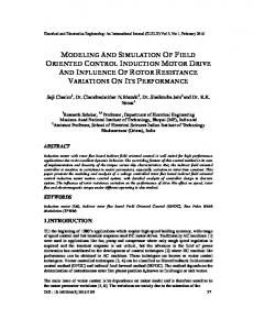
be sufficiently assumed that torque production is due to the fundamental sequence plane only. IV. CONTROL SCHEME OF FIVE-PHASE IM-IFOC Since torque production mainly belongs to the fundamental sequence plane, the multiphase induction machine can be controlled using vector control exactly similar to three-phase induction machine using only fundamental sequence (k = 1) and with an appropriate transformation [4]. For proper orientation at steady state, the following equations are hold [3] 𝜆𝑞𝑟1 = 𝑝𝜆𝑞𝑟1 = 0 . (4) Substituting for fundamental sequence into (2c) and (2d) (5a) 0 = 𝑟𝑟1 𝑖𝑑𝑟1 + 𝑝𝜆𝑑𝑟1 (5b) 0 = 𝑟𝑟1 𝑖𝑞𝑟1 + (𝜔𝑒 − 𝜔𝑟 )𝜆𝑑𝑟1 . From flux linkage equations, the following relations can be deduced 𝜆𝑑𝑟1 − 𝐿𝑚1 𝑖𝑑𝑠1 𝐿𝑚1 𝑖𝑑𝑟1 = , 𝑖𝑞𝑟1 = − 𝑖 (6) 𝐿𝑟1 𝐿𝑟1 𝑞𝑠1 Hence 𝐿𝑚1 𝜆𝑑𝑟1 = 𝑖 (7) (1 + 𝜏𝑟1 𝑝) 𝑑𝑠1 where, 𝜏𝑟1 = 𝐿𝑟1 ⁄𝑟𝑟1 and the slip speed of the fundamental plane is 𝐿𝑚1 𝜔𝑠𝑙1 = 𝑖 (8) 𝜏𝑟1 𝜆𝑑𝑟1 𝑞𝑠1 At steady state, if the rotor flux is properly aligned to the direct axis, the rotor current is perpendicular to the rotor flux and its direct axis component becomes zero, hence (9) 𝜆𝑑𝑟1 = 𝐿𝑚1 𝑖𝑑𝑠1 An essential requirement for an IFOC is to continuously determine the synchronous frame rotor axis angle θe1. For the common situation where the motor shaft has a mechanical speed/position encoder, this angle can be calculated by integrating the slip frequency specified by (8) for any particular λdr1 and iqs1, to calculate a slip angle. This angle is then added to the measured rotor “electrical” speed angle to continuously calculate an estimated θe1 [11] 𝑟𝑟 𝐿𝑚1 𝜃𝑒1 = 𝜃𝑟1 + ∫ 𝑠𝜔𝑒1 𝑑𝑡 = 𝜃𝑟1 + ∫ 𝑖𝑞𝑠1 𝑑𝑡 . (10) 𝐿𝑟1 𝜆𝑑𝑟1 Fig. 1 shows the schematic diagram of the proposed control scheme. The outer speed control loop is applied to generate the reference motor-stator q-axis current (iqs1*). Since the flux of the machine is kept constant, the motor-stator daxis current (ids1*) can be calculated according to (11) ∗ (11) 𝑖𝑑𝑠1 = 𝜆∗𝑑𝑟1 ⁄𝐿𝑚1 . The obtained dq reference currents will then be compared with the measured dq motor stator current through PI controllers to assure proper current sharing and to avoid rotor flux mismatch [9]. The output of these controllers is then used to compute the inverter dq currents.
2102
5-ph CSI g1
Idc* Idc* λds1*
1/Lm1
ids1 ωr*
iqs1*
PI
+-
iqs1
Iac*
Eqn. (15)
ids1*
-+ +-
+-
IC Ci
Gating Signals Generator
X mabcde
iinvq*
Synchronous frame rotor axis angle
iqs1*
5-ph IM
θe1
mabcde* Iac
ωr
ids1*
Is
g1 - - - - - - - - g10 Eqn. (16)
PI
Leg-A g6
M
Iac
iinvd*
PI
PI
Iinv
Eqn. (17)
ids1
θe1
iqs1
Eqn. (10)
Fig. 1. Proposed control scheme of five-phase IM-IFOC. vcd1 VC_abcde vcq1 θe1
ids1
iqs1* iqs1
θe1 icq1
ωe1
-+
PI
++
+-
PI
++
icq1
md Eqn. (13)
icd1
ids1*
The main drawback in this method is the determination of Kdc which is arbitrarily chosen and the need for capacitor currents calculation through measurements. The proposed control method in this paper is in a dotted rectangular in Fig. 1. In the proposed method, the modulation index (m) is initially set to unity, and the inverter current is assumed to be the motor current thus the following relation is obtained
icd1
Eqn. (12)
iinvd* Eqn. (14)
mabcde
mq
Idc*
iinvq*
∗ ∗ 2 2 𝐼𝑎𝑐 = √𝑖𝑖𝑛𝑣𝑑 + 𝑖𝑖𝑛𝑣𝑞 = 𝐼𝑑𝑐 .
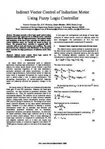
Fig. 2. Conventional CSI-based IM-IFOC.
For proper inverter current calculation, the capacitor current should be compensated. The conventional compensation method can be done as in three-phase IM-IFOC [9], shown in Fig. 2, by measuring the five-phase capacitor voltages (VC_abcde) then transforming them to dq reference frame using θe1 calculated in (10). Hence, the dq capacitor currents are (12) 𝑖𝑐𝑑1 = −𝜔𝑒1 𝐶𝑉𝑐𝑞1 , 𝑖𝑐𝑞1 = 𝜔𝑒1 𝐶𝑉𝑐𝑑1 Adding the dq capacitor currents in (12) to the PI controller outputs yields to inverter dq current calculation. This value is used in (13) to estimate the modulation index in dq 𝑖𝑖𝑛𝑣𝑞 𝑖𝑖𝑛𝑣𝑑 𝑚𝑑 = , 𝑚𝑞 = . (13) 2 2 2 2 √𝑖𝑖𝑛𝑣𝑑 + 𝑖𝑖𝑛𝑣𝑞 √𝑖𝑖𝑛𝑣𝑑 + 𝑖𝑖𝑛𝑣𝑞 Consequently the corresponding modulating signals (mabcde) are calculated by transforming back the inverter dq currents. The dq modulation index values are then transformed to abcde frame and fed to the gating signal generator. The reference DC-current (Idc*) is assumed to be [9] ∗ 2 2 𝐼𝑑𝑐 = 𝐾𝑑𝑐 √𝑖𝑖𝑛𝑣𝑑 + 𝑖𝑖𝑛𝑣𝑞 ,
𝐾𝑑𝑐 > 1
(15)
Consequently the corresponding modulating signals (mabcde) are calculated by transforming back the inverter dq currents to abcde frame, then the transformed currents are divided by Idc* as follows 𝑖𝑖𝑛𝑣_𝑎𝑏𝑐𝑑𝑒 𝑚𝑎𝑏𝑐𝑑𝑒 = . (16) ∗ 𝐼𝑑𝑐 In order to generate the proper modulating signals (mabcde*) that will compensate for the capacitor currents and define the relationship between the DC-link current and the per-phase motor peak current, a modulation index controller is applied as in Fig. 1. The controller forces the measured per-phase motor peak current (Iac) to follow Iac*, then generates a corrective factor for the modulation index with value M. This value is multiplied by the initially generated modulating signals, mabcde with unity amplitude, to generate the reference modulating signal, mabcde*, that will be fed to the gating signal generator. Thus, without any measurement, the per-phase motor peak current can be calculated as
(14)
2103
2 2 𝐼𝑎𝑐 = √𝑖𝑑𝑠1 + 𝑖𝑞𝑠1 .
(17)
TABLE I. SYSTEM PARAMETERS Induction Motor parameters:
200
Ref. Speed
Motor speed
180
Rated power
1.5 HP
Rated Torque Rated phase Voltage (rms)
7 N.m 110 V
Rated Frequency (f1)
60 Hz
Number of poles (P)
4
Applied Flux (𝜆𝑑𝑟1 )
0.55 wb
Stator resistance (rs) and inductance (ls)
2.6 Ω and 5 mH
60
Rotor resistance (rr1) and inductance (lr1)
1.88 Ω and 23.6 mH
40
Rotor resistance (rr3) and inductance (lr3)
0.83 Ω and 10.4 mH
20
Mutual Inductance (Lm1), (Lm3)
149.6mH and 13.5 mH
160
Speed (rad/s)
140 120 100 80
0
0
1
2
3
CSI parameters:
4
5
6
7
Time (s)
Carrier switching frequency (fc)
750 Hz
Filter Capacitor (Ci)
40 μF
Fig. 3. Speed controller response. 6 ids1 *
5.5
V.
SIMULATION RESULTS
ids1
5
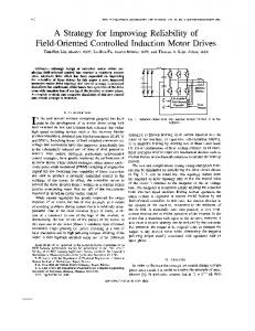
A simulation model for a prototype five-phase machine was built in MATLAB/SIMULINK to justify the control scheme discussed above. The same prototype will be used for experimental verification in future work. The IM parameters and other component values are given in Table I. The reference motor speed is set to 160 rad/s and the load torque is changed as follows Interval-I: 𝑇𝐿 = 0 N. m for 0 > 𝑡 ≥ 4𝑠. Interval-II: 𝑇𝐿 = 7 N. m for 𝑡 > 4𝑠.
Current (A)
4 3.5 3 2.5 2 1.5 1
2
2.5
3
3.5
4 Time (s)
4.5
5
5.5
6
Fig. 4. d-axis current controller response. 8 iqs1 *
iqs1
6 4
Current (A)
During these Intervals the speed controller response, the dq current controllers response, the modulation index controller response, the five-phase IM voltages, the five-phase IM currents, the IM flux, the applied inverter modulating signal with modulation index (M), the IM electromagnetic torque are all monitored. The simulation figures show that the proposed control scheme variables follow their references. The speed response is shown in Fig. 3. The dq-current components are given in Figs. 4 and 5 respectively, while the modulation index is shown in Fig. 6. The five-phase currents and voltages are shown in Figs. 7 and 8 respectively. Each figure explores the no-load case, interval-I shown in sub-figure (a), and the load case, interval-II shown in sub-figure (b). The five-phase currents and voltages in both cases are balanced. Because of the application of the decoupled dq current control, the dq motor currents are forced to follow their assigned references, which ensure a complete decoupling and a proper field orientation. Fig. 9 shows the motor electromagnetic torque, which is zero in Interval-I and 7 N.m in Interval-II as expected. Since the phase currents are sinusoidal the motor torque is ripple free. Fig. 10 shows the motor rotor flux which is kept constant during the two intervals. Generally in CSI-drives it is common to compensate for the capacitor currents, this can be done, conventionally, by measuring the capacitor voltages, transforming them to dq frame, and then calculating the dq capacitor currents.
4.5
2
0 -2 -4 2
2.5
3
3.5
4 Time (s)
4.5
5
5.5
6
Fig. 5. q-axis current controller response.
These calculated values will be added to the motor dq reference currents to calculate the required inverter dq currents. These measuring and calculating processes are avoided in the proposed control scheme, where a modulation index controller is applied. The modulation index controller forces the measured perphase motor peak current to follow the reference per-phase motor peak current. Since the dq currents are already required for the dq current controllers, the measured per-phase motor peak current can be calculated without additional current sensors.
2104
10
200 iac *
9
iac
150
8 100 6
50
Voltage (V)
Current (A)
7
5 4
0 -50
3 -100 2 -150
1 0
2
2.5
3
3.5
4 Time (s)
4.5
5
5.5
-200 3.95 3.955
6
3.96
3.965
3.97
Fig. 6. Modulation index controller response.
3.99
3.995
4
6.985
6.99
6.995
7
250 200
4
150
3 2
100
1
50
Voltage (V)
Current (A)
3.985
(a)
5
0 -1 -2
0 -50 -100
-3
-150
-4
-200
-5 3.95 3.955
3.975 3.98 Time (s)
3.96
3.965
3.97
3.975 3.98 Time (s)
3.985
3.99
3.995
-250 6.95 6.955
4
(a)
6.96
6.965
6.97
6.975 6.98 Time (s)
(b) Fig. 8. Motor five-phase voltages (Vabcde) (a) Interval I and (b) Interval II.
5
15
4
Electromagnetic Torque (N.m)
3
Current (A)
2 1 0 -1 -2 -3 -4
5
0
-5
-5 6.95 6.955
10
6.96
6.965
6.97
6.975 6.98 Time (s)
6.985
6.99
6.995
7
1
(b) Fig. 7. Motor five-phase currents (Iabcde) (a) Interval I and (b) Interval II.
2
3
4 Time (s)
5
6
7
Fig. 9. Motor electromagnetic torque (Tem).
Fig. 11 shows the five-phase CSI reference modulating signals with the proper corrective factor (M). VI. CONCLUSION In this paper, a control scheme based on conventional IFOC of five-phase induction machine is presented using fivephase SPWM-CSI. Mapping for SPWM-CSI is applied for proper gating signal generation. The proposed control scheme provides balanced motor stator five-phase voltages and currents. The proposed control scheme not only maintains the lower torque ripples featured by multiphase motors, but also
reduces the measurement and calculation burden required for calculating the required inverter current. The motor air-gap flux and electromagnetic torque are effectively decoupled. The presence of the modulation index controller not only allows linear modulation index control, but also avoids the need for the capacitor current measurements. The switching frequency is quite low, which is a desired feature required in CSIs. Thus, the proposed control scheme can be applied to MV drives. Due to page limitations, the full study of system dynamics and stability will be tackled in future work.
2105
[7] [8]
0.55 0.5
[9]
Flux (wb)
0.45 0.4
[10]
0.35
[11]
0.3
[12] 0.25 0.2
0
1
2
3 4 Time (s)
5
6
[13]
7
[14]
Fig. 10. Motor rotor flux (λdr1).
IX. BIOGRAPHIES
2
M. A. Elgenedy was born in Alexandria-Egypt in June 1985. He received his B.Sc. (first class honors) and M.Sc. degrees in Electrical Engineering from Alexandria University, Egypt in 2007 and 2010 respectively. Currently he is working as a research associate with Texas A&M University at Qatar. From 2007 to 2013, he was an assistant lecturer in Electrical Engineering Department, Faculty of Engineering, Alexandria University. In 2012, he also joined Spiretronic LLC as a research engineer. His research interests are electric machine drives, energy conversion, renewable energy, smart grids and power quality.
1.5
Modulation index (pu)
1 0.5 0 -0.5 -1 -1.5 -2
2
2.5
3
3.5
4 Time (s)
4.5
5
5.5
6
Fig. 11. Reference modulating signal, mabcde*, with corrective factor M.
VII.
ACKNOWLEDGMENT
This publication was made possible by NPRP grant # [4 941 - 2 - 356] from the Qatar National Research Fund (a member of Qatar Foundation). The statements made herein are solely the responsibility of the authors. VIII. [1] [2] [3]
[4] [5]
[6]
REFERENCES
E. Levi, R. Bojoi, F. Profumo, H. A. Toliyat, and S. Williamson, “Multiphase induction motor drives—A technology status review,” IET Electr. Power Appl., vol. 1, no. 4, pp. 489–516, Jul. 2007. M. J. Duran, F. Salas, and M. R. Arahal, “Bifurcation analysis of fivephase induction motor drives with third harmonic injection,” IEEE Trans. Ind. Electron., vol. 55, no. 2, pp. 2006–2014, May 2008. A. S. Abdel-Khalik, A. S. Morsy, S. Ahmed, and A. M. Massoud, “Effect of stator winding connection on performance of five-phase induction machines,” IEEE Trans. Ind. Electron., vol. 61, no. 1, pp. 3– 19, Jan. 2014. G. K. Singh, K. Nam, and S. K. Lim, “A simple indirect field-oriented control scheme for multiphase induction machine,” IEEE Trans. Ind. Electron., vol. 52, no. 4, pp. 1177–1184, Aug. 2005. L. Zheng, J. E. Fletcher, B. W. Williams, and X. He, “A novel direct torque control scheme for a sensorless five-phase induction motor drive,” IEEE Trans. Ind. Electron., vol. 58, no. 2, pp. 503–513, Feb. 2011. E. Levi, M. Jones, A. Iqbal, S. N. Vukosavic, and H. A. Toliyat, “Modeling, control, and experimental investigation of a five-phase series-connected two-motor drive with single inverter supply,” IEEE Trans. Ind. Electron., vol. 54, no. 3, pp. 1504–15016, Jun. 2007.
Ayman S. Abdel-Khalik (SM’12) was born in Alexandria-Egypt in July 1979. He received his B.Sc, and M.Sc. degrees in Electrical Engineering from Alexandria University, Egypt in 2001 and 2004 respectively. He received his Ph.D degree in May 2009 under a dual channel program between Alexandria University and Strathclyde University, Glasgow, UK. Dr. Abdel-khalik is currently a lecturer in Electrical Engineering Department, Faculty of Engineering, Alexandria University. In 2009, he also joined Spiretronic LLC as a senior research scientist. His research interests are electrical machine design, electric machine simulation, mathematical modeling, and electric drives. Ahmed Massoud (SM’11) received the B.Sc. (first class honors) and M.Sc. degrees from the Faculty of Engineering, Alexandria University, Egypt, in 1997 and 2000, respectively, and the Ph.D. degree in electrical engineering from the Computing and Electrical Department, Heriot-Watt University, Edinburgh, U.K., in 2004. From 2005 to 2008, he was a Research Fellow at Strathclyde University, Glasgow, U.K. From 2008 to 2009, he was a Research Fellow at Texas A&M at Qatar, Doha, Qatar. From 2009 to 2012, he was an Assistant Professor at the Department of Electrical Engineering, College of Engineering, Qatar University, where he is currently an Associate Professor in the same department. His research interests include Power Electronics, Energy Conversion, Renewable Energy and Power Quality. Shehab Ahmed (SM'12) was born in Kuwait City, Kuwait in July 1976. He received the B.Sc. degree in Electrical Engineering from Alexandria University, Alexandria, Egypt, in 1999; the M.Sc. and Ph.D. degrees from the Department of Electrical & Computer Engineering, Texas A&M University, College Station, TX in 2000 and 2007, respectively. From 2001 to 2007, he was with Schlumberger Technology Corporation working on downhole mechatronic systems. He is currently an Assistant Professor with Texas A&M University at Qatar, Doha, Qatar. His research interests include mechatronics, solid-state power conversion, electric machines, and drives.
2106 Powered by TCPDF (www.tcpdf.org)
M. Jones, S. N. Vukosavic, and E. Levi, “Parallel-connected multiphase multidrive systems with single inverter supply,” IEEE Trans. Ind. Electron., vol. 56, no. 6, pp. 2047–2057, Jun. 2009. S. Dwari, and L. Parsa, “Fault-tolerant control of five-phase permanentmagnet motors with trapezoidal back emf,” IEEE Trans. Ind. Electron., vol. 58, no. 2, pp. 476–485, Feb. 2011. A. Abdelsalam, M. Masoud, M. Hamad, and B. Williams, “Modified indirect vector control technique for current-source induction motor drive ,” IEEE Trans. Ind. Appl., vol. 48, no. 6, pp. 2433–2442, Nov./Dec. 2012. M. A. Elgenedy, A. Abdel-Khalik, A. Elserougi , S. Ahmed, and A. M. Massoud, “Fault-tolerant control of five-phase current source inverter for medium-voltage drives,” in Conf. PEMD, 2014. B.Wu, High-Power Converters and AC Drives, New York/Piscataway, NJ: Wiley/IEEE Press, 2006. J. R. Espinoza, G. Joos, “Current source converter on-line pattern generator switching frequency minimization,” IEEE Trans. Ind. Electron., vol. 44, no. 2, April 1997. M. I. Masoud, “On-line carrier based PWM gating signal generator for multi-phase current source inverter”, in Conf. MEPCON, 2012. M. I. Masoud, and A. S. Abdel-Khalik, “Vector controlled five-phase PWM-CSI induction motor drive,” in Conf. POWERENG, 2013.