Case 3âAnnular Flow. The time responses for liquid super- .... tional Meeting on Multiphase Flow, Cannes, France, June 7â9, pp. 307â327. 4 Marti, S., Erdal, F., ...
Shoubo Wang Ram S. Mohan Ovadia Shoham Petroleum Engineering and Mechanical Engineering Department, The University of Tulsa, Tulsa, OK 74104
Jack D. Marrelli Texaco E&P Technology Division, Humble, TX 77338
Gene E. Kouba Chevron Petroleum Technology Company, Houston, TX 77082
Performance Improvement of Gas Liquid Cylindrical Cyclone Separators Using Integrated Level and Pressure Control Systems The performance of gas-liquid cylindrical cyclone (GLCC©1) separators for two-phase flow metering loop can be improved by eliminating liquid overflow into the gas leg or gas blow-out through the liquid leg, utilizing suitable integrated control systems. In this study, a new integrated control system has been developed for the GLCC, in which the control is achieved by a liquid control valve in the liquid discharge line and a gas control valve in the gas discharge line. Simulation studies demonstrate that the integrated level and pressure control system is highly desirable for slugging conditions. This strategy will enable the GLCC to operate at constant pressure so as not to restrict well flow and simultaneously prevent liquid carry-over and gas carry-under. Detailed experimental studies have been conducted to evaluate the improvement in the GLCC operational envelope for liquid carry-over with the integrated level and pressure control system. The results demonstrate that the GLCC equipped with integrated control system is capable of controlling the liquid level and GLCC pressure for a wide range of flow conditions. The experimental results also show that the operational envelope for liquid carry-over is improved twofold at higher liquid flow rate region and higher gas flow rate region. GLCC performance is also evaluated by measuring the operational envelope for onset of gas carry-under. 关S0195-0738共00兲00804-9兴
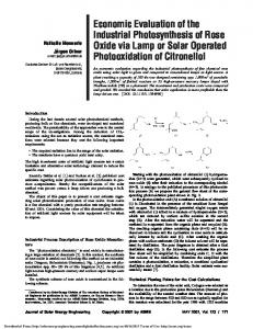
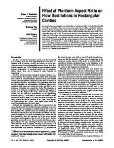
Introduction Conventional vessel-type separators, which are bulky, heavy, and expensive, have been used by the petroleum industry for many years. Recently, development of innovative alternatives to the conventional separators such as the GLCC have been sought due to economic and operational pressures. The GLCC is becoming more popular as it is simple, compact, has low weight and low cost, requires little maintenance, and is easy to install and operate. Also, the GLCC reduces the inventory of hydrocarbons significantly, which is critical for environmental and safety considerations. Figure 1 shows a GLCC separator test unit equipped with control systems built at The University of Tulsa. It is a vertically installed pipe mounted with a downward inclined tangential inlet, with outlets provided at the top and bottom of the pipe. It has neither moving parts nor internal devices. As it passes through the tangential inlet, the flow forms a swirling motion, producing centrifugal forces separating the two phases of the incoming mixture. The heavier liquid phase is forced radially towards the walls of the cylinder and is collected from the bottom, while the lighter gas phase moves to the center of the cyclone and is taken out from the top. Control valves are located in the gas and liquid outlets for GLCC control. GLCC has several potential applications as gas and/or liquid knockout systems upstream of production equipment, multiphase meters, multiphase pumps, and de-sanders. It is also used as portable well testing equipment, flare gas scrubbers, and slug catchers. The GLCC has potential for downhole separation, primary surface separation 共onshore and offshore兲, and subsea separation. 1 GLCC—gas liquid cylindrical cyclone—copyright, The University of Tulsa, 1994 Contributed by the Petroleum Division and presented at the ETCE/OMAE2000, New Orleans, Louisiana, February 14–17, 2000, of THE AMERICAN SOCIETY OF MECHANICAL ENGINEERS. Manuscript received by the Petroleum Division, October 28, 1999; revised manuscript received July 11, 2000. Associate Technical Editor: C. Sarica.
Previous studies 关1,2兴 of GLCCs have been carried out for loop configurations, such as in the multiphase metering loop, characterized by recombination of the gas and liquid streams at the outlet. The significance of this configuration lies in the fact that the liquid level can be self-regulated for small flow rate variations. However, for large flow variations, there is an increasing need for liquid level control to improve the GLCC loop operation so as to prevent liquid overflow through the gas leg and/or gas blow-out through the liquid leg. Also, for field applications other than metering, separated outlets of the gas and liquid streams are needed. This configuration must have liquid level control for efficient operation, as the GLCC has very small residence time. In this investigation, a new integrated control system has been developed for the GLCC, in which the control is achieved by a liquid control valve 共LCV兲 in the liquid discharge line and a gas
Fig. 1 TUSTP test facility with control systems
Journal of Energy Resources Technology Copyright © 2000 by ASME
DECEMBER 2000, Vol. 122 Õ 185
control valve 共GCV兲 in the gas discharge line. A control strategy is proposed and a mathematical model is formulated for liquid level control using GCV in gas leg. Detailed control system design and simulation studies are also conducted to evaluate the integrated control system performance for different flow conditions. Another objective of this study is to conduct detailed experimental investigations to evaluate the improvement in the GLCC operational envelope for liquid carry-over with the integrated level and pressure control system for a wide range of flow conditions. GLCC performance is also evaluated by measuring the operational envelope for onset of gas carry-under. A brief review of the relevant literature pertaining to this area is provided in the next chapter.
Literature Review A detailed review of the literature on separation technology is given by Arpandi et al. 关1兴, Kouba and Shoham 关2兴, Kouba et al. 关3兴, and Marti et al. 关4兴. Compact separators have been used for several applications such as offshore production, 关5,6兴, aqueous aluminum silver oxide battery systems, 关7兴, and gas-liquid separation systems, 关8,9兴. Experimental studies on the hydrodynamic flow behavior in the GLCC are presented in Marti et al. 关4兴, Gomez 关10兴, Erdal et al. 关11兴, and Chirinos et al. 关12兴. Even though several investigators have realized that the performance of compact separators could be improved by incorporating suitable control systems, only a few control studies have been conducted. Kolpak 关13兴 developed a hydrostatic model for passive control of compact separators in a metering loop configuration. This model provides the sensitivity of the liquid level to the gas and liquid inflow rates. Genceli et al. 关14兴 developed a dynamic model for a slug catcher. The system response of slug catchers was found to be quite slow because of the large residence time of the big vessel. Few other studies have been conducted on the control applications for the process industry dealing with only single-phase liquid flow and allow the liquid level to change between some ranges, 关15,16兴, which avoid overflow or draw up of the liquid from the tank. As a control system is crucial for GLCC operation, there have been few investigations recently on design, simulation, and analysis of GLCC level and pressure control. Mohan et al. 关17兴 have developed a passive control system and demonstrated that it is capable of enhancing the operational envelope for liquid carry-
over. Wang 关18兴 has conducted a detailed analysis for stability and transient response of GLCC active control system. The current authors 关19兴 have developed a mathematical model for design and simulation of dynamic performance of GLCC control system; they 关20兴 have also developed different control strategies and control system simulators for GLCC applications. From the foregoing, it could be noted that compact multiphase separation technology research remains a critical problem for the petroleum industry as it is capable of improving the optimization and productivity of the industry. It has also been demonstrated that the performance of compact separators could be enhanced considerably by incorporating control systems. More research needs to be conducted to understand and optimize the complex GLCC control system design and simulation. An overview of the integrated control system design for GLCC level and pressure control is presented in the forthcoming, followed by a discussion of the experimental results.
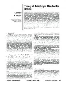
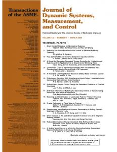
Control System Design Wang et al. 关19兴 provided the detailed mathematical model and controller design for liquid level control by LCV and pressure control by GCV. Figure 2 shows the block diagram of integrated liquid level control by both LCV and GCV. For this configuration, the liquid level is input to both the LCV control loop and the GCV control loop. Initially for simplicity, the GCV control loop and LCV control loop are designed assuming that both loops are isolated from the integrated system. The detailed mathematical description and derivation of the links between the LCV and GCV control loops of integrated system are provided in 关20兴. In the current study, the mathematical model and controller design for liquid level control by GCV is given. The block diagram of the isolated GCV control loop for liquid level control is shown in Fig. 3. The real liquid level measured by the sensor/transmitter is compared with the set point. The resulting error signal is then sent to GCV controller to control the gas outflow rate by changing the control valve position. By assuming a constant gas inflow rate 共this assumption is valid for gas dominated system兲, the GLCC pressure can be related to the gas outflow rate by a simple gas mass balance and can be solved by the equation of state. If the LCV position is assumed to be constant, the liquid outflow rate is
Fig. 2 Block diagram of integrated level control by both GCV and LCV
186 Õ Vol. 122, DECEMBER 2000
Transactions of the ASME
Fig. 3 Block diagram of liquid level control system by GCV
Fig. 4 Linearized model of GLCC level control by GCV
only a function of the GLCC pressure. The liquid level is related by the liquid mass balance and can be solved by the geometry of the GLCC. Mathematical Model. Figure 4 shows the block diagram of the GCV control loop in Laplace domain. Wang et al. 关19,20兴 provided the mathematical descriptions of all the blocks of the system and the linearization procedure. Controller Design. The controller design is performed for a GLCC at TUSTP test facility, 3 in. in diameter, 7 ft tall, and with a single inlet. The response times of both LCV and GCV have been experimentally determined to be 2 s. The time delay of the pneumatic transmission line and the actuator is assumed to be 1 s. The open loop transfer function of the GCV control loop for liquid level control can be derived from a linearized model in Laplace domain similar to the LCV control loop 关19兴 as follows: G 共 s 兲 H 共 s 兲 ⫽K c
冉
s 2 s⫹
k 1 Co
冊冉 冊 s⫹
1 o
PD Controller Design. A PD controller can be designed for a fast response system based on the root locus shown in Fig. 6. Suitable design gain can be chosen to match the system transient response and the controller settings can be calculated as follows: PD 共 s 兲 ⫽K c 共 1⫹T D s 兲 ⫽K D 共 s⫹z c 兲
(2)
The time response for the system with one PD is shown in Fig. 8 共plot 1兲. As can be seen, the settling time for the system is more
(1)
where K c is the controller gain, k⫽D 1 D 3 D 4 D 5 G/C o o is the system gain, and G⫽ 关 ⌬C v /⌬ 兴 ⫽ set(100/H max⫺Hmin). It may be noted that the open loop transfer function for the GCV control loop is a second order system, whereas it was a first order system for LCV control loop. Based on the system open loop transfer function, Eq. 共1兲, the root locus of the system can be plotted as shown in Fig. 5. One path of the root locus is always in the unstable region, which is the right half of the s-plane. This implies that the system is always unstable for a simple controller proportional gain. In order to make the system stable it is necessary to add a zero close to the origin to compensate one pole at the origin. A compensator zero of 0.02 is picked and the resulting new root locus is shown in Fig. 6. As can be seen, a very small part of the root locus moves to the stable region, which is the left half of the s plane. In this case for some range of the compensator gain, the system could be stable. But the stability is very sensitive Journal of Energy Resources Technology
to the system gain. If the system gain changes because of the changes of operational conditions or system parameters, which could happen in real life, the system can easily move to the unstable region. By adding a second compensator zero at 0.1, the root locus is completely moved to the stable region. The root locus for this case is shown in Fig. 7.
Fig. 5 Root locus without compensator
DECEMBER 2000, Vol. 122 Õ 187
than 40 s, which is very large and is not appropriate for slug flow conditions. This performance can be improved by designing a cascaded PD controller. Cascaded PD Controller Design. The root locus for cascaded PD controller design is shown in Fig. 7. The mathematical expression for two cascaded PD controllers is given by PD 1 共 s 兲 PD 2 共 s 兲 ⫽K c1 K c2 共 1⫹T D1 s 兲共 1⫹T D2 s 兲 ⫽K D 共 s⫹z c1 兲共 s⫹z c2 兲
(3)
Comparing both sides of Eq. 共3兲, the PD settings of the cascaded PD controller can be determined. The step response of the system with two PDs is shown in Fig. 8 共plot 2兲. It can be seen that the settling time for this configuration is less than 10 s, which is highly desirable for slug flow conditions.
Experimental Studies Fig. 6 Root locus with one PD compensator
Experimental Facility. The experimental facility consists of a standard two-phase flow loop, test section, and a data acquisition system. Test Section. Figure 9 shows the GLCC test section. The GLCC body is a 3-in. pipe with an inclined tangential aluminum inlet. There are a gas flow meter and a gas control valve on the gas leg. Similarly, there are a liquid flow meter and a liquid control valve on the liquid leg. The outlet section can be recombined or separated depending upon the application. For a two-phase metering loop, the liquid and gas streams are recombined. For full separation configuration, the liquid and the gas outlets are separated. There is an absolute pressure transducer on the top of the GLCC and a differential pressure transducer across the GLCC for sensing the liquid level.
Fig. 7 Root locus with two PD compensators
Data Acquisition System. The data acquisition system used for the test is LabView DAS National Instrument with Control Tool Kit. Figure 10 shows the schematics of the data acquisition system. A GCV and an LCV are used to control the upstream gas and liquid flow rates. Two MicroMotion mass flow meters measure the upstream liquid and gas flow rates. In the test section, the down stream LCV and GCV are controlled by the LabView Program based on the operating conditions. All the data from the metering section and the test section are acquired and logged in an Excel file. Integrated System Simulation. With the designed controller settings, the real system behavior can be simulated by using the integrated control system simulator. Wang et al. 关20兴 developed the integrated control system simulators for different control strategies. The TUSTP GLCC data is input to the integrated liquid level and pressure control and the simulator response is obtained. The system response for slug unit input is shown in Fig. 11. As can be seen, the liquid level and GLCC pressure are maintained within the design range, which indicates that the control system design is valid for slug flow condition. Experimental Results. The experimental results include the liquid level, pressure, LCV and GCV time responses, and operational envelopes for liquid carry over at different operating conditions.
Fig. 8 Step response for liquid level control by GCV
188 Õ Vol. 122, DECEMBER 2000
System Time Responses. Figures 12共a兲, 共b兲, and 共c兲, plots 1–4, show the liquid level, pressure, GCV, and LCV time responses for different flow conditions. Plot 1 is the liquid level, plot 2 is the pressure, plot 3 is the GCV percent closing, and plot 4 is the LCV percent opening. For different combinations of liquid and gas flow rates, the inlet flow pattern is different. It could be slug flow, churn flow, or annular flow. The experimental investigations are conducted at three different flow conditions: slug, churn, and annular. Transactions of the ASME
Fig. 9 Experimental facility „GLCC metering loop…
Case 1—Slug Flow. The time responses for liquid superficial velocity V sl ⫽1.98 ft/s and gas superficial velocity V sg ⫽10.75 ft/s are shown in Fig. 12共a兲. As can be seen, the liquid level 共plot 1兲 and pressure 共plot 2兲 fluctuate around the set points. The range of the liquid level fluctuation is about 15 in. and that of the pressure is around 3 psi. When the liquid slug enters the GLCC, the liquid flow rate increases and the gas flow rate decreases. As a result, the liquid level rises from its set point 共25
in.兲, and the pressure falls from its set points 共25 psia兲. And also the LCV opens to dump the liquid and the GCV closes to raise the pressure. When a gas pocket hits the GLCC, the gas flow rate increases and liquid flow rate decreases. As a result, the pressure will rise and liquid level will fall. So, the LCV closes to bring the liquid level up and the GCV opens to release the pressure. The LCV average opening is about 66 percent. The range of the LCV position fluctuation around the set point is less than 15 percent.
Fig. 10 Data acquisition and control system flow chart
Journal of Energy Resources Technology
DECEMBER 2000, Vol. 122 Õ 189
Fig. 11 Time responses for slug input
The GCV average opening is about 58 percent. The fluctuation around the set point is less than 5 percent. This trend demonstrates that the liquid level and GLCC pressure are well controlled with less dynamics of the control valves, which is ideal for enhancing the control valve life. Case 2—Churn Flow. The time responses for liquid superficial velocity, V sl ⫽1.0 ft/s, and gas superficial velocity, V sg ⫽17.76 ft/s, are shown in Fig. 12共b兲. The liquid level and pressure have less fluctuation compared to case 1. The GCV opening is almost constant, about 64 percent, because the gas flow rate is steady 共and high兲 and the pressure stays constant. The LCV opening fluctuates between 40 and 75 percent. The average opening is 58 percent. The level is well controlled at the expense of larger LCV dynamics, which will reduce the lifetime of the control valve. The trade off is that if some range of liquid level fluctuation can be tolerated, the controller gain can be reduced causing lesser control valve dynamics. Case 3—Annular Flow. The time responses for liquid superficial velocity, V sl ⫽0.6 ft/s, and gas superficial velocity, V sg ⫽28.8 ft/s, are shown in Fig. 12共c兲. The liquid level and pressure are quite steady because the inflow rates are steady. The GCV opening is 73 percent. The LCV opening is 53 percent and has less dynamics. From these three cases, it can be seen that the control system is capable of controlling the liquid level and GLCC pressure over a wide range of flow conditions. It may also be noted that the control valve positions are dynamically changed to match the corresponding flow conditions. For extreme flow conditions 共very high or very low兲, the control valve positions will be out of the normal operating range, say 30–75 percent opening. This will lead to loss of controllability. However, the system can be brought back to controllable range by changing the GLCC pressure set point. Al190 Õ Vol. 122, DECEMBER 2000
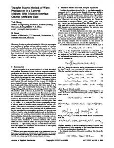
ternatively, integrated liquid level control strategy by both LCV and GCV can be adopted as described in 关20兴 to address this problem. Operational Envelope for Liquid Carry-Over. Liquid carryover is the initiation of liquid entrainment into the discharged gas stream at the top of the GLCC. It occurs under extreme operating conditions of high gas and/or high liquid flow rates. The operational envelope for liquid-carry over is obtained by plotting the locus of the liquid and gas flow rates at which liquid carry-over is initiated. The area below the envelope is the region of normal operating conditions, where no liquid carry-over is experienced in the GLCC. The region above the operational envelope represents the flow conditions for continuous liquid carry-over. The operational envelopes for different operating conditions are shown in Fig. 13. Recombined Outlets (No Liquid Level Control). For a recombined outlet metering loop, the liquid level can be self-regulated by pressure balance across the liquid and gas legs for normal flow conditions. For this case, the maximum liquid flow rate for liquid carry-over initiation is 1.5 ft/s, corresponding to a liquid level of 58 in. The liquid carry-over mechanism is by churning flow in the upper part of the GLCC. When the gas flow rate is increased to 15 ft/s 共corresponding to a liquid flow rate of 1.2 ft/s兲, the liquid level is below the inlet. The liquid carry-over is in the form of liquid droplets due to annular flow. When the gas flow rate reaches 20 ft/s 共corresponding to a liquid flow rate of 0.8 ft/s兲, the liquid level is about 25 in. The liquid will blow out from the liquid leg if the gas flow increases beyond this point, indicating the termination of the operational envelope. Separated Outlets (With Liquid Level Control). If the liquid and gas outlets are separated, the liquid level cannot be selfTransactions of the ASME
Fig. 13 Operational envelope for liquid carry-over
rises and as the tangential velocity reduces, liquid falls down from the top of the vortex crown, blocking the inlet. As a result, the incoming gas blows the liquid droplets out of the gas leg promoting liquid carry-over. In the high gas flow rate and low liquid flow rate region, the liquid carry-over is by annular flow. Between these two regions, the liquid carry-over mechanism is a combination of the two mechanisms. The liquid carry-over operational envelope overlaps for the cases of with and without level control, when the liquid level is below the inlet. This indicates that if the liquid level is far below the inlet 共6 in.兲, the operational envelope for liquid carry-over is independent of the liquid level. Recombined Outlets (With Liquid Level Control). If the metering loop is equipped with a control system, which has a recombined gas and liquid outlets, the operational envelope overlaps with the case of separated gas and liquid outlet case. This indicates that the outlet condition does not affect the liquid carry-over operational envelope. Operational Envelope for Gas Carry-Under. The gas carryunder curve is the initiation of gas entertainment into the liquid stream at the bottom of the GLCC. This is characterized by observation of a big gas core at the lower part of the GLCC. Above the gas carry-under envelope, substantial amount of gas is carried into the liquid stream in the form of gas bubbles.
Conclusions
Fig. 12 Time responses for integrated level and pressure control
regulating, and liquid level control is needed for proper operation. The operational envelopes for two cases of separated outlet configuration, namely, a level set point of 40 and 25 in. are shown in Fig. 13. The operational envelopes for both these cases overlap for the entire gas and liquid flow conditions. As can be seen, if the liquid level is controlled below the inlet, 40 or 25 in., the gas and liquid flow rates operational envelope increases almost twofold. In the high liquid flow rate region, the liquid carry-over mechanism is caused by the mixing process of the gas and liquid at the inlet. Because of the high liquid tangential velocity, the vortex crown Journal of Energy Resources Technology
A new control strategy has been developed for liquid level control by using GCV on the gas leg. A linearized mathematical model has been derived for the controller design of the gas control loop. The control system design has been conducted for stability and transient response characteristics, and its performance is verified by simulating the integrated control system for slug input. A detailed experimental study has been conducted using a newly developed GLCC with active control system and a computerized data acquisition system. Time responses for integrated liquid level and pressure control system and GLCC operational envelopes for liquid carry-over and gas carry-under are determined experimentally. The experimental results show that the control system is capable of controlling the liquid level and GLCC pressure over a wide range of flow conditions—slug flow, churn flow, and annular flow. The time responses of the liquid level and the pressure show that more flow disturbance will cause more dynamics of the system. Extreme flow conditions 共very high or very low兲 will lead to loss of controllability. The system can be brought back to a conDECEMBER 2000, Vol. 122 Õ 191
trollable range by changing the GLCC pressure set point, or by incorporating an integrated liquid level control strategy by both LCV and GCV. The liquid level can be well controlled at the expense of larger LCV dynamics, which will reduce the life of the control valve. If liquid level fluctuation can be tolerated over a wider range, the controller gain can be suitably designed causing lesser control valve dynamics. By using the control system, the GLCC operational envelope for liquid carry-over can be increased twofold in the high liquid and gas flow regions. When the liquid level is below the inlet, the operational envelopes for different outlet configurations overlap each other.
Acknowledgments The authors wish to thank Tulsa University Separation Technology Projects 共TUSTP兲 member companies for supporting this project. The authors also acknowledge the National Petroleum Technology Office 共NPTO兲, U.S. Department of Energy 共DOE兲 for the Grant: DE-FG22-97BC15024.
Nomenclature Co Cv Cg D1 D2 D3 D4 D5
⫽ ⫽ ⫽ ⫽ ⫽ ⫽ ⫽ ⫽
e H KD Kc P Q s t TD v z o ⌬
⫽ ⫽ ⫽ ⫽ ⫽ ⫽ ⫽ ⫽ ⫽ ⫽ ⫽ ⫽ ⫽ ⫽ ⫽
time constant of control valve, t, s liquid control valve flow coefficient gas control valve flow coefficient constant transfer function for liquid flow equation constant transfer function for GLCC geometry constant transfer function for gas flow equation constant transfer function for gas mass balance constant transfer function for pressure to liquid outflow rate controller error, m/Lt 2 , psi liquid level, L, ft design gain from root locus controller gain GLCC pressure, m/Lt 2 , psig volumetric flow rate, L 3 /t, ft3/s Laplace variable time, t, s derivative time, t, s velocity, L/t, ft/s root locus zero time constant, t, s incremental deviation position of control valve stem, percent GLCC system gain
Subscripts c G L max min in out
⫽ ⫽ ⫽ ⫽ ⫽ ⫽ ⫽
controller gas liquid maximum minimum in to GLCC out of GLCC
192 Õ Vol. 122, DECEMBER 2000
s, set ⫽ set point value o ⫽ initial value v ⫽ valve
References 关1兴 Arpandi, I. A., Joshi, A. R., Shoham, O., Shirazi, S., and Kouba, G. E., 1995, ‘‘Hydrodynamics of Two-Phase Flow in Gas-Liquid Cylindrical Cyclone Separators,’’ SPE 30683, presented at SPE 70th Annual Meeting, Dallas, TX, October 22–26; 1996, SPEJ, Dec., pp. 427–436. 关2兴 Kouba, G. E., and Shoham, O., 1996, ‘‘A Review of Gas-Liquid Cylindrical Cyclone 共GLCC兲 Technology,’’ presented at the Production Separation Systems International Conference, Aberdeen, England, April 23–24. 关3兴 Kouba, G. E., Shoham, O., and Shirazi, S., 1995, ‘‘Design and Performance of Gas-Liquid Cylindrical Cyclone Separators,’’ Proc. BHR Group 7th International Meeting on Multiphase Flow, Cannes, France, June 7–9, pp. 307–327. 关4兴 Marti, S., Erdal, F., Shoham, O., Shirazi, S., and Kouba, G., 1996, ‘‘Analysis of Gas Carry-Under in Gas-Liquid Cylindrical Cyclones,’’ presented at the Hydrocyclones 1996 International Meeting, St. John College, Cambridge, England, April 2–4. 关5兴 Davies, E. E., 1985, ‘‘Compact Separators for Offshore Production,’’ 2nd, New Technology for the Exploration & Exploitation of Oil and Gas Resources Symposium, London, Eng., BP Research Center, pp. 621–629. Proceedings, Vol. 1. 关6兴 Oranje, I. L., 1990, ‘‘Cyclone-Type Separators Score High in Comparative Tests,’’ Oil Gas J., 88, No. 4, January 22, pp. 54–57. 关7兴 Bandopadhyay, P. R., Pacifico, G. C., and Gad-el-Hak, M., 1994, ‘‘Sensitivity of a Gas-Core Vortex in a Cyclone-Type Gas-Liquid Separato,’’ Advanced Technology and Prototyping Division, Naval Undersea Warfare Center Division, Newport, RI. 关8兴 Fekete, L. A., 1986, ‘‘Vortex Tube Separator May Solve Weight Space Limitations,’’ World Oil, July, pp. 40–44. 关9兴 Zhikarev, A. S., Kutepov, A. M., and Solov’ev, V., 1985, ‘‘Design of a Cyclone Separator for the Separation of Gas-Liquid Mixtures,’’ Chem. Petroleum Eng., 21, No. 3/4 Mar., pp. 196–198. 关10兴 Gomez, L. E., 1998, ‘‘A State-of-the Art Simulator and Field Application Design of Gas-Liquid Cylindrical Cyclone Separators,’’ M. S. thesis, The University of Tulsa. 关11兴 Erdal, F., Shirazi, S., Shoham, O., and Kouba, G, 1996, ‘‘CFD Simulation of Single-Phase and Two-Phase in Gas-Liquid Cylindrical Cyclone Separators,’’ SPE 36645, presented at the SPE 71st Annual Meeting, Denver, CO, October 6–9; 1997, SPE J., 2, pp. 436–446. 关12兴 Chirinos, W. A., Gomez, L. E., Wang, S., Mohan, R., Shoham, O., and Kouba, G. E., 1999, ‘‘Liquid Carry-over in Gas-Liquid Cylindrical Cyclone Compact Separators,’’ SPE 56582, presented at the SPE 74th Annual Meeting, Houston, TX, October 3–6. 关13兴 Kolpak, M. M., 1994, ‘‘Passive Level Control in Two-Phase Separator,’’ internal communication, Arco Exploration and Production Technology. 关14兴 Genceli, H., Kuenhold, K., Shoham, O., and Brill, J. P., 1988, ‘‘Dynamic Simulation of Slug Catcher Behavior,’’ presented at the SPE 63rd Annual Meeting, Houston, TX, October 2–5. 关15兴 Roy, S., and Smith, C., 1995, ‘‘Better Than Averaging Level Control,’’ University of South Florida, in Tech. 关16兴 Galichet, S., Foulloy, L., Chebre, M., and Beauchene, J. P., ‘‘Fuzzy Logic Control of a Floating Level in a Refinery Tank,’’ Proc. IEEE International Conference on Fuzzy Systems, pp. 1538–1542. 关17兴 Mohan, R., Wang, S., Shoham, O., and Kouba, G., 1998, ‘‘Design and Performance of Passive Control System for Gas-Liquid Cylindrical Cyclone Separators,’’ ASME J. Energy Resour. Technol., 120, Mar., pp. 49–55. 关18兴 Wang, S., 1997, ‘‘Control System Analysis of Gas-Liquid Cylindrical Cyclone Separators,’’ M. S. thesis, The University of Tulsa. 关19兴 Wang, S., Mohan, R., Shoham, O., and Kouba, G., 1998, ‘‘Dynamic Simulation and Control System Design of Gas-Liquid Cylindrical Cyclone Separators,’’ SPE 49175, presented at the SPE 73rd Annual Meeting, New Orleans, LA, September 27–30. 关20兴 Wang, S., Mohan, R., Shoham, O., Marrelli, J., and Kouba, G., 2000, ‘‘Control System Simulators for Gas-Liquid Cylindrical Cyclone Separators,’’ ASME ETCE/OMAE Conference, New Orleans, LA, February 1–2.
Transactions of the ASME