swept volume is developed using advanced sweeping/skinning techniques. Semi- ... Tradition- ally, machining verifications were performed by first examining ... mercial CAD/CAM software CATIA to determine the boundary of engaged surface ...
B. M. Imani1 Ph.D. Candidate
M. A. Elbestawi Professor, Fellow ASME Intelligent Machines and Manufacturing Research Center (IMMRC), Department of Mechanical Engineering, McMaster University, Hamilton, Ontario, Canada L8S 4L7
1
Geometric Simulation of Ball-End Milling Operations In this paper, B-rep solid modeling techniques are used to deal with geometric modeling issues encountered in ball-end milling simulation. The precise B-rep model of the cutter swept volume is developed using advanced sweeping/skinning techniques. Semi-finishing operations are simulated by performing consecutive Boolean operations between the updated part and swept volume. The instantaneous chip geometry is accurately and reliably extracted from the B-rep model of the updated part. Also, the material removal in ball-end milling is precisely simulated for finishing operations, in order to construct the feed-mark and scallop geometries. The validity of the final model is confirmed by comparing the predicted feed-mark profile with experimental measurements. The system developed can be used to verify and optimize NC codes, thus contributing to improving reliability, accuracy, and productivity in CNC machining. 关DOI: 10.1115/1.1347034兴
Introduction
Various commercial CAM systems are widely used to generate numerical control 共NC兲 codes to machine complicated and low quantity parts such as dies and molds. Although the current state of CAM technology is capable of generating tool paths for freeform 共or sculptured兲 surfaces with prescribed tolerances, the NC codes may still contain shortcomings due to interactions among the workpiece, cutters, and the machine tool structure. Traditionally, machining verifications were performed by first examining the generated tool paths overlaid on the workpiece drawings and then proof-running tests conducted on soft materials prior to actual machining operations. However, as identifying significant errors was performed manually, the procedure was time-consuming and prone to errors. With the development of solid modeling techniques which provide a reliable model-based environment for 3D part representation, the focus gradually shifted to pre-process machining simulation and verification systems. In solid modeling, one of the most widely used methods for 3D part representation is Boundary Representation 共B-rep兲 for the following reasons. B-rep can support a variety of mathematical surfaces including the most versatile one, i.e., nonuniform rational B-spline 共NURBS兲. Also, in the B-rep data structure faces and edges are readily available together with a wealth of algorithms and functions, to either extract required geometric information or modify the 3D model of workpiece. For example, the swept objects encountered in CAM applications are effectively modeled in the B-rep. In the work presented a 3D B-rep geometric kernel 共ACIS兲, developed by Spatial Technology Inc., is used as a geometric engine to simulate the machining process. ACIS can support the NURBS as well as analytical surfaces. The new applications can interact with ACIS in C⫹⫹, interpreter Scheme language or a combination of both. Relevant published research work in geometric modeling of machining processes can be summarized as follows. Bertok et al. 关1兴 proposed a torque prediction system based on the geometric simulation of the flat-end milling operation. Their geometric model was able to compute the removed volume per tooth for simple geometries. The swept volume of solids of revolution was investigated by Wang 关2兴 and Wang and Wang 关3兴. Based on the equation of surfaces representing the boundary of the solid and the motion function 共feed兲, a family of curves lying on the envelope of the moving surface was generated. The authors then constructed the 3D pixel space swept volume which was used for subsequent Boolean operations. However, their spatial partition1 Currently Assistant Professor, Ferdowsi University, Mashhad, Iran. Contributed by the Manufacturing Engineering Division for publication in the JOURNAL OF MANUFACTURING SCIENCE AND ENGINEERING. Manuscript received October 1997; revised February 2000. Associate Editor: K. Ehmann.
ing approach is view-dependent, i.e., in the case of changing the eye-view, the entire representation must be reconstructed which limits its applications. Huang and Oliver 关4兴 also used the spatial partitioning approach to assess NC milling errors. The instances of the tool are generated along the tool path which is used consecutively in updating the part by one-dimensional regularized Boolean operations. They overcome the view dependency problem by introducing a contour display method. To accelerate the machining simulation and verification, Menon and Robinson 关5兴 enhanced the work by Menon and Voelcker 关6兴 with parallel computation. They also extended the range of verification to the machining tolerance and static deflection assessments. Takata et al. 关7兴 and Tsai et al. 关8,9兴 also developed a milling simulation system to predict instantaneous cutting forces. The geometric simulation was based on a method which combines the z-buffer technique and swept volume generation. Although the above spatial partitioning approaches degrade much more slowly with the complexity of the updated workpiece as opposed to the B-rep, and it is relatively easy to implement parallel spatial partitioning, these methods generate an approximated representation of 3D solids. To increase the level of precision, a large amount of memory is required. Based on Constructive Solid Geometry 共CSG兲 part representation, Spence 关10兴 performed computer simulations of flat-end milling operations. The instantaneous immersion geometry 共entry and exit angles兲 was computed using a semi-circle sweeping the tool path. Ball-end milling simulation was reported in ElMounayri et al. 关11兴 using a B-rep polyhedral-based solid modeler. The removed volume was computed and the cutting edge, modeled with a cubic Bezier curve, was intersected with the volume to find the in-cut segments. Studies for 3-axis chip geometry calculation are limited to Feng and Menq 关12兴. They used a commercial CAD/CAM software 共CATIA兲 to determine the boundary of engaged surface between tool and workpiece. The in-cut segments were then computed using the boundary curves. However, the geometric calculations were not based on an informationally complete 共B-rep兲 model of in-process part. An accurate B-rep model of an in-process part together with accurate tool geometry are two essential requirements for obtaining accurate and valid chip geometry. The aim of the geometric simulation system developed in the current work is: 共1兲 to accurately represent various geometric objects, for example the cutter swept volume, required for comprehensive simulation of 3-axis ball-end milling; 共2兲 to update the part for each NC block or a group of NC blocks; 共3兲 to calculate the instantaneous chip geometry, i.e., in-cut segments and undeformed chip thickness, required for physical simulation of machining process; and also 共4兲 to construct the model of feed marks and scallops on the machined surface in order to estimate the surface quality.
Journal of Manufacturing Science and Engineering Copyright © 2001 by ASME
MAY 2001, Vol. 123 Õ 177
Downloaded 04 Dec 2009 to 194.225.128.135. Redistribution subject to ASME license or copyright; see http://www.asme.org/terms/Terms_Use.cfm
The bottleneck of most available B-rep modelers is the Boolean operation. B-rep modelers can reliably handle analytical forms where the closed-form 共or exact兲 representations of entities, such as surface-surface intersections are available. However, when they are dealing with free-form surfaces, the exact representation of entities is not possible. Therefore, an approximated piecewise entity fitted to points on the exact geometry is constructed. In general, the main reason for the failure of applications such as part updating, chip geometry calculation, and feed-mark construction in machining simulation, is large approximation 共or fitting兲 tolerances. To maintain the advantages of B-rep techniques and overcome the limitation, the current research proposes an improved swept volume generation method. In the developed method, boundary faces of the swept volume are constructed using advanced sweeping/skinning techniques. In addition to position data, derivative constraints are imposed in order to improve approximation tolerances. Henceforth, the paper is organized as follows. The 3-axis swept volume generation is discussed in Section 2 followed by the part updating process implemented on one quarter of a die with sculptured surfaces in Section 3. The instantaneous chip geometry is computed based on an informationally complete model of updated part in Section 4. In Section 5 feed marks and scallops are modeled and the surface quality is evaluated. The last section concludes the paper and proposes future research work.
2
3-Axis Swept Volume Generation
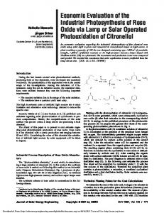
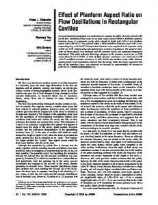
The kinematics of the milling operation consists of a rotational motion of cutting edges and translational motion of the workpiece 共ignoring the tool run-out and deflections兲. This system can be replaced by an equivalent system in which the workpiece is stationary and the cutting edges have simultaneous rotational and translational motions. Thus, the true path of points on the cutting edge for 2-axis milling is trochoidal, as demonstrated by Martellotti 关13兴. Since the material is removed by trochoidal path of consecutive cutting edges, cusps 共or feed marks兲 with the spacing of feed per tooth are generated on the machined surface. To precisely simulate the material removal of milling operations, the volume removed must be constructed based on the true path of each point on the cutting edge. However, for the nonfunctional surfaces, the cusp height is either one or two order of magnitude smaller than dimensional tolerances 关14兴. Therefore, the true swept volume can be simplified as the volume generated by a translational sweeping motion of a solid of revolution, which was proposed by Wang 关2兴 and Menon and Voelcker 关6兴. For the case of ball-end milling the solid of revolution 共i.e., cutter兲, consists of a cylinder and a semi-sphere representing the envelope of rotating cutting edges on the cylindrical and spherical parts of the ball-end mill. In general, ten faces are required for the construction of a valid 3-axis cutter swept volume, as shown in Fig. 1. The boundary of swept volume consists of two categories of faces. Analytical faces 共Faces 5 to 10兲 represent portions of the cutter at initial and final positions. These planar, cylindrical, or spherical faces are supported in the geometric kernel. The second category 共Faces 1 to 4兲 are tool path dependent. The current work proposes to use advanced sweeping/skinning techniques to construct precise NURBS representation of these faces which results in a higher level of precision. In the following the detailed procedure of constructing Face 1 which represents the swept surface by the ballnose will be discussed. A general form of swept surface is given by s 共 u, v 兲 ⫽T共 v 兲 ⫹A共 v 兲 C共 u 兲
(1)
where C(u), T( v ), and A( v ) denote the section curve, path curve, and general transformation matrix, respectively. Thus, isoparametric curves on the swept surface s(u, v ) are instances of C(u) transformed by A( v ) and translated by T( v ). As A( v ) is 178 Õ Vol. 123, MAY 2001
Fig. 1 3-axis cutter swept volume and its boundary faces
generally not representable in NURBS form, a NURBS approximation to s(u, v ) must be constructed. This research adopts advanced skinning techniques in which the accuracy of resulting face is improved by imposing path derivative constraints at each data point. For Face 1 the section curve, C(u), is a semi-circle. In general, conic sections can be exactly represented in quadratic rational B-splines 关15兴. However, there is no obvious technique to impose path 共or v -direction兲 derivative constraints for rational B-splines 关16兴. Due to this limitation, quadratic nonrational B-splines are chosen to interpolate the semi-circle. Thus, the interpolated section curve can be expressed by n
C共 u 兲 ⫽
兺 PN i⫽0
i
i,2共 u 兲
(2)
The B-spline representation of section curve also allows us to implement the method for any form tool. It is assumed that the tool path 共path curve兲 is given and represented in cubic NURBS form: T共 v 兲 ⫽
m⬘ 兺 i⫽0 w i Qi Ni,3共 v 兲 m⬘ 兺 i⫽0 w i Ni,3共 v 兲
(3)
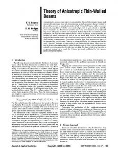
where m ⬘ ⫹1 is the number of control points. K⫹1 instances of C(u) are transformed and positioned along T( v ) at parameter value of 兵 v k 其 , k⫽0, . . . ,K. The 兵 v k 其 spacing affects the skinning tolerance. For the current implementation equal spacing is considered. To construct A( v ), a local Cartesian coordinate system 兵 o( v k ),x( v k ),y( v k ),z( v k ) 其 in terms of the global coordinate system, 兵O, X, Y, Z其 is introduced. The origin of the local coordinate system is placed at T( v k ) and three orthonormal unit vectors are defined as follows. y( v k ) is the unit vector tangent to the path in the feed direction. x( v k ) is a horizontal unit vector normal to y( v k ). Lastly, z( v k ) is a unit vector which makes a right-hand coordinate system with x and y: o共 v k 兲 ⫽T共 v k 兲 y共 v k 兲 ⫽ x共 v k 兲 ⫽
T⬘ 共 v k 兲 兩 T⬘ 共 v k 兲 兩 kˆ⫻y共 v k 兲
兩 kˆ⫻y共 v k 兲 兩
z共 v k 兲 ⫽x共 v k 兲 ⫻y共 v k 兲
(4)
For further details refer to Siltanen and Woodward 关17兴. Having constructed the local coordinate system 共see also Fig. 2兲, we can Transactions of the ASME
Downloaded 04 Dec 2009 to 194.225.128.135. Redistribution subject to ASME license or copyright; see http://www.asme.org/terms/Terms_Use.cfm
Fig. 2 Global and local coordinate systems
compute the general transformation matrix, A( v k ). Rows of A( v k ) are the unit vectors of the local coordinate system: A共 v k 兲 ⫽ 兵 x共 v k 兲 ,y共 v k 兲 ,z共 v k 兲 其 T
(5)
In the next step, control points of the section curve, Pi , are transformed by A( v k ) to orient the section curve perpendicular to the tool path and then translated by T( v k ) to place the center of section curve at o( v k ): Pi,k ⫽T共 v k 兲 ⫹A共 v k 兲 Pi
(6)
where Pi,k , i⫽0, . . . ,n, are control points of the kth semi-circle instance. Then, for each i and k a derivative vector, Di,k , is computed based on the tangent to the tool path at v k , i.e. Dk ⫽T⬘ 共 v k 兲
(7)
All Di,k are parallel to Dk and their magnitudes are adjusted according to following relation to reflect relative distance d k ⫽ 兩 Pk ⫺Pk⫺1 兩 Di,0⫽
兩 Pi,1⫺Pi,0兩 D0 d1
n
兺
i⫽0
兩 Pi,k ⫺Pi,k⫺1 兩 di
k⫽0, . . . ,K⫺1 ¯v 0 ⫽0 ¯v K ⫽1
(9)
K
兺 兩P
i,k ⫺Pi,k⫺1 兩
A satisfactory choice of the knot vector considering the distribution of 兵¯v k 其 proposed by Piegl and Tiller 关16兴 is Journal of Manufacturing Science and Engineering
冎
(10)
The last step in skinning Face 1 is to solve the following system of linear equations for each i. There are 2(K⫹1) known data items 共i.e., Pi,k and Di,k 兲 and 2(K⫹1) unknown control points Qi, j , j⫽0, . . . ,m, (m⫽2K⫹1) m
Pi,k ⫽
兺Q
Di,k ⫽
兺Q
(8)
1 n⫹1
k⫽1
¯v K⫺2 ⫹2¯v K⫺1 ¯v K⫺1 ⫹1 , ,1,1,1,1 3 2
j⫽0
vk兲 i, j N j,p 共 ¯
j⫽0
vk兲 i, j N⬘j,p 共 ¯
(11)
Finally, the swept/skinned surface representing Face 1 can be expressed by
Imposing the derivative constraints based on above equations ensures that all partial derivatives with respect to v on the kth isoparametric curve are parallel to Dk 关16兴. For the v -directional interpolation, in addition to the degree (p⫽3), the parameter values of interpolating points 兵¯v k 其 and the knot vector V⫽ 兵 v i 其 , which is a nondecreasing set of real numbers over which B-spline basis functions are defined, are required. The ¯v k are computed by the averaging method
d i⫽
⫻
¯v 1 2¯v 1 ⫹¯v 2 ¯v 1 ⫹2¯v 2 , , , ..., 2 3 3
k⫽0, . . . ,K i⫽0, . . . ,n
兩 Pi,k⫹1 ⫺Pi,k 兩 ⫹ 兩 Pi,k ⫺Pi,k⫺1 兩 Di,k ⫽ Dk d k⫹1 ⫹d k
¯v k ⫽¯v k⫺1 ⫹
再
V⫽ 0,0,0,0,
m
兩 Pi,K ⫺Pi,K⫺1 兩 Di,K ⫽ DK dK
i⫽0, . . . ,n k⫽0, . . . ,K
Fig. 3 Improving fitting approximation in interpolating a semicircle
n
sˆ共 u, v 兲 ⫽
m
兺兺Q i⫽0 j⫽0
i, j Ni,2共 u 兲 Ni,3共 v 兲
(12)
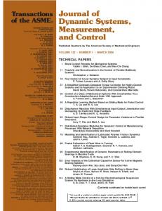
The same argument can be followed for sweeping/skinning Faces 2 to 4 except the section curves representing the cylindrical part of the cutter are linear. In order to investigate the improvement of the technique, the fitting approximation of the section curve of Face 1 共i.e., the semicircle兲 is compared with the same curve interpolated by a cubic B-spline. The fitting tolerance of the cubic B-spline in ACIS is set to one micron. Figure 3 compares the fitting approximation of the quadratic B-spline curve computed by the technique proposed in this section with the fitting approximation of the interpolated cubic B-spline. Although both curves have the same number of control points, the fitting approximation of our method is improved to 0.2 microns. After generating all the boundary faces, an ACIS ‘‘stitching’’ operation is used to generate a topologically valid swept volume. The validity of the swept volume is verified by checking its topology before performing a Boolean subtraction between the B-rep model of part and the cutter swept volume. MAY 2001, Vol. 123 Õ 179
Downloaded 04 Dec 2009 to 194.225.128.135. Redistribution subject to ASME license or copyright; see http://www.asme.org/terms/Terms_Use.cfm
3
Part Updating Process
One quarter of a die with a sculptured surface cavity has been chosen to illustrate the part updating process for the 3-axis ballend milling operation. It is assumed that rough-cut pocketing operations with flat-end mills were used to remove the inside material 共Fig. 4兲. These operations leave right angle shoulders on the part surface which can be precisely represented by B-rep, NURBS enhanced solid modeling techniques. Also, it is assumed that 3-axis ball-end milling tool paths are generated to remove the shoulders.
Fig. 6 Scallop height variation for 3-axis tool path
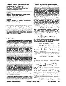
Fig. 4 Rough-cut updated part
In the part updating process, the swept volume is first constructed. The B-spline tool path used for the swept volume represents a few blocks of the NC code. The number of blocks depends on the part geometry. The Boolean subtraction between part and swept volume is then performed which consecutively updates the part 共Fig. 5共a兲兲. Thus, it is possible to observe the precise simulation of the machining operation step-by-step. And, in case of any error, corrective actions can be taken prior to actual machining. During part updating, consecutive Boolean subtractions increase the number of faces in the updated part data structure 共Fig. 5共a兲兲. As a result, the time required for subsequent operations increases. For example, it is required to find the intersecting pair of faces before performing the face-face intersection of the Boolean operation. A fast algorithm for reporting all intersecting pairs first constructs the iso-box of each face, including the faces of the updated part and the query face, and then reports the intersecting pairs. Based on the sweep paradigm, the query time for reporting all intersection is O(n log2(n)⫹J) 关18兴, where n is the number of faces in the updated part and J is the number of intersections. In the developed simulator, the NURBS surfaces generated during consecutive updating are unified and represented by one NURBS surface for each tool path 共Fig. 5共b兲兲. Thus, the size of the B-rep data structure decreases which results in faster query time. The semi-finished B-rep model of the part includes valuable information for tool path planning of the following operation, i.e., finishing. Removing a shoulder with a ball-end mill leaves two scallops on the surface as depicted in the Fig. 6. The scallop geometry can precisely by represented by the B-rep techniques. Thus, the scallop height defined as the normal distance between a point on the scallop edge and the design surface can be extracted from the B-rep model. Figure 6 illustrates the scallop height variation for the given 3-axis tool path, refer to 关19兴 for details of the tool path generation technique. The B-rep model, therefore, can assist the finishing tool path planning in order to achieve higher metal removal rate 共MRR兲 and smaller scallop heights.
4
Fig. 5 Semi-finished updated part
180 Õ Vol. 123, MAY 2001
Instantaneous Chip Geometry Calculation
The required geometric information for the physical simulation of the machining process includes: 共1兲 tool geometry, such as the cutting edge design and 共2兲 chip geometry, i.e., in-cut segment of the cutting edge and undeformed radial chip thickness. The procedure for determining the above geometric information is as follows. Transactions of the ASME
Downloaded 04 Dec 2009 to 194.225.128.135. Redistribution subject to ASME license or copyright; see http://www.asme.org/terms/Terms_Use.cfm
path. In order to obtain accurate and reliable chip geometry, it is essential to construct a B-rep model of the workpiece and update it as the tool removes material. In addition to the updated workpiece, the chip geometry depends on the cutting edge design, the tool path, and the feed.
Fig. 7 Instantaneous in-cut segment extraction for ball-end milling
4.2.1 In-cut Segment. The instantaneous in-cut segment 共the engaged portion of the cutting edge during machining兲 is computed in two steps. First, the boundary of the contact face between the ball end mill and the part is constructed. In 2- or 3-axis ballend milling this boundary consists of two B-spline edges and one circular edge 共Fig. 7兲. The B-splines are intersections of the cutter with faces of the updated part. The circular edge is the boundary where the cutting edge either leaves or enters the part. This edge is constructed using the B-spline endpoints, the cutter radius and the slope of tool path. The second step is to find the intersection points of the interpolated cutting edge with the boundary of the contact face. The edge-edge intersection function finds the closest point on the edges with a prescribed tolerance. The segments on the cutting edge are then classified into in-cut and out-of-cut segments 共in-cut segments are shown in Fig. 7兲. The endpoints of each in-cut segment represent the integration limits required for the physical simulation of the machining process. 4.2.2 Undeformed Chip Thickness. The instantaneous undeformed radial chip thickness is one of the most important parameters affecting the cutting forces. Martellotti 关13兴 derived the following equation for the chip thickness by assuming a circular path for the tooth: t c 共 兲 ⫽R⫹ f t sin ⫺ 共 R 2 ⫺ f t2 cos2 兲 1/2
Fig. 8 Variation of chip thickness for 3-axis milling
4.1 Tool Geometry. Tool geometric information can either be provided by the manufacturer or by direct measurement of points on the cutting edge and rake face and fitting a curve or surface 共i.e., B-spline curve or surface兲 to the measured points. In this work, a constant lead ball-end milling cutter, widely used for semi-finishing operations, has been utilized. This analytical form (cutter diameter⫻ /tan(0)⫽Lead) is not supported by the geometric modeler. Thus, it is replaced with a cubic piecewise NURBS curve. Ten points on the edge together with initial conditions, i.e., slopes of the edge at start and end points, are used to interpolate the cutting edge. 4.2 Chip Geometry. In 3-axis machining of sculptured surfaces, the chip geometry is continuously varying along the tool
(13)
where R, f t , and are tool radius, feed per tooth and edge angular position, respectively. For practical face milling operations the above relationship was further simplified to t c 共 兲 ⬇ f t sin
(14)
For the case of 3-axis ball-end milling Feng and Menq 关12兴 considered the effect of the vertical component of feed on the chip thickness using the following simplified relationship t c 共 ,z 兲 ⬇R 2 共 z 兲 ⫺R 1 共 z 兲 ⫹ f h sin
(15)
f h is the horizontal component of the feed along the tool path. R 1 and R 2 are the ball-nose radii at two successive positions in the same z value as shown in Fig. 8. However, as decreases, the amount of error in the above approximation increases. Figure 9共a兲 and 共b兲 depicts the approximation errors for equal to 90, and 45 deg. The accurate representation is obtained by skinning a
Fig. 9 Chip thickness-comparison of simplified and accurate representation at different angular positions
Journal of Manufacturing Science and Engineering
MAY 2001, Vol. 123 Õ 181
Downloaded 04 Dec 2009 to 194.225.128.135. Redistribution subject to ASME license or copyright; see http://www.asme.org/terms/Terms_Use.cfm
B-spline surface to instances of the cutting edge while rotating with the cutting speed and translating with the feed. The accurate chip thickness can then be obtained using two successive surfaces representing the accurate cutting edge motion. However, the extraction of instantaneous chip thickness from the accurate representation is computationally inefficient. Thus, a modified equation which can accurately calculate this chip thickness at any angular position as compared to the above method is used: t c 共 ,z 兲 ⫽R 2 共 z 兲 ⫹ f h sin ⫺ 关 R 21 共 z 兲 ⫺ f 2h cos2 共 兲兴 1/2
(16)
Figure 9共b兲 also shows that the amount of error in the above approximation with respect to the value obtained by accurate representation is negligible at equal to 45 deg.
5
Surface Texture Representation
In the milling operation, the surface texture defined in terms of roughness, waviness, lay and flaws, deteriorates due to several factors, e.g., built-up edge formation, dynamics of structure, periodic engagements of the cutting edge 关20兴. In the following, the procedure of updating the B-rep model of the part for finishing operation is proposed. The method is able to precisely construct the feed mark geometry as well as cross-feed scallop geometry. The feed mark profile is extracted from the B-rep model and compared with the experimental measurements. Also, the effects of feed and tool diameter variations on the peak-to-valley maximum height (R max ) are investigated. In the last section the B-rep model of surface texture for a free-form surface is constructed and the feed mark profile is extracted. 5.1 B-rep Model of Feed Marks and Scallops in Finishing. In the finishing operation of sculptured surfaces, ball-nose cutters are extensively used. For these cutters, the inserts are designed to produce a radius within a certain tolerance on the workpiece. The cutting edge of the insert used in the experiment is one quarter of a circle which is tilted by 3 deg, 共Fig. 10兲. The surface swept by the cutting edge is constructed through skinning n instances of the cutting edge 共in the current work n is equal to 21兲, which are transformed according to true cutting motions of the edge. In addition to primary cutting and translational feed motions, the tool run-outs and tool deflections influence the cutting edge position 关21兴. Due to the fact that in the finishing operation the resultant cutting forces are one order of magnitude smaller that the resultant cutting forces in roughing and semi-finishing operations, the contribution of deflections is ignored in the current work. Thus, the ith transformation matrix corresponding to the edge angular position i can be expressed by
Tr共 i 兲 ⫽
冋
cos共 i 兲
⫺sin共 i 兲
0
e sin共 ⫺ e 兲
sin共 i 兲
cos共 i 兲
0
fty ⫹e cos共 ⫺ e 兲
0
0
1
ftz
0
0
0
1
册
Fig. 11 Surface swept by the cutting edge
fty ⫽
ft cos共 兲 i 360
ftz ⫽
ft sin共 兲 i 360
(18)
where is the uphill angle. The transformation matrix also includes the tool radial run-out e which has e degrees lag with respect to the cutting edge. Figure 11 shows the skinned surface generated for the total rotation angle of 183 deg where the cutting takes place. The extra 3 deg are to compensate for the cutting edge tilt angle. To avoid the surface degeneration at the ball-nose tip, the area within 5 deg to the vertical axis is omitted. In the next step the sheet body of the skinned surface is generated. Then, a copy of the sheet body for each tool rotation is generated and transformed along the tool path. The spacing between copies is the feed ft in case of 3-axis milling. Thus, the material removal process of ball-end milling can be precisely simulated by performing consecutive Boolean subtractions between the part and the transformed copies of the sheet body. Figure 12 illustrates the final B-rep model of the workpiece which includes feed mark and cross-feed scallop geometries. Although the proposed method is implemented for a 3-axis milling operation, it can be extended to 4- and 5-axis milling by modifying the transformation matrix 关Eq. 共17兲兴. 5.2 Feed Mark Profile. The faces readily available in the B-rep model precisely represent the feed marks on the surface. To
(17)
assuming that the feed motion lies in yz plane and is given by
Fig. 10 Insert geometry
182 Õ Vol. 123, MAY 2001
Fig. 12
B -rep model of feed marks and cross-feed scallops
Transactions of the ASME
Downloaded 04 Dec 2009 to 194.225.128.135. Redistribution subject to ASME license or copyright; see http://www.asme.org/terms/Terms_Use.cfm
Fig. 13 Surface roughness profile
obtain the feed mark profile, these faces can be intersected with a vertical plane aligned with feed direction. The resulting intersection curves represent the feed marks profile. The cutting conditions used for the simulation and experimentation are as follows. Down-milling with a 12.7 mm diameter ball-end mill is performed with 1.59 mm radial width of cut. The depth of cut is maintained at 1.27 mm while cutting the uphill angle of 20 deg. The feeds are 0.127, 0.191, and 0.254 mm/rev with a cutting speed of 10000 RPM. Also, the radial run-out measured for the experimental setup was found to be 0.012 mm with 40 deg lag with respect to the cutting edge. Figure 13 depicts the measured feed mark profile using a stylus contact-type profilometer. On the average, the values of the spacing 共or wavelength兲 and pick-to-valley predicted by the simulation are within 5 to 10 percent of the values measured by the profilometer. The good accordance between predicted and measured quantities validates the accuracy of the geometric simulation. Small discrepancies in the pick-to-valley values can be due to the fact that in the experimental setup, there was an inevitable small misalignment between the arm of the profilometer and the feed direction. The important parameters in ball-end milling which influence the feed mark profile are feed and tool diameter while the uphill angle does not have much effects, 关22兴. The surface representing R max variations with respect to feed and tool diameter is illustrated in Fig. 14 for the range used in practice. It has been
Fig. 14 Variation of peak-to-valley R max with feed and tool diameter
Journal of Manufacturing Science and Engineering
Fig. 15
B -rep model of surface texture on a free-form surface
observed that R max gradually decreases with tool diameter while it sharply increases with feed. 5.3 Simulation of Surface Texture on Free-Form Surfaces. In this section, the developed methods and algorithms are used to simulate surface texture of a workpiece with a free-form surface 共see Fig. 15兲. In practice, four- or five-axis tool path strategies are implemented for finishing operations to keep the dead zone of the ball-nose cutter, the area within 15 deg to the tool axis, out of the cut. For the above workpiece one-way tool paths aligned with y-axis are generated. Also, the ball-nose is tilted ⫺15 deg around the x-axis at each tool position. Thus, the dead zone of the cutter is not engaged. The cutting conditions used for the simulation are: down-milling with a 12.7 mm diameter ball-end mill, 1.59 mm radial width of cut, 1.27 mm depth of cut, and 0.508 mm/rev feed. The sheet body of the skinned face is computed using the method explained in Section 5.1. The transformation matrix 关Eq. 共17兲兴 is modified to include the variations of the feed direction and the surface normal at each position. The extra tilt of the ball-nose is also considered in the matrix. The material removal is simulated by performing Boolean subtraction between the workpiece and the
Fig. 16 Feed-mark profile extracted from the B -rep model
MAY 2001, Vol. 123 Õ 183
Downloaded 04 Dec 2009 to 194.225.128.135. Redistribution subject to ASME license or copyright; see http://www.asme.org/terms/Terms_Use.cfm
sheet bodies computed at each tool position. Figure 15 illustrates the B-rep model of surface texture at a desired spot. The B-rep model is intersected with a vertical plane aligned with the feed direction to generate the feed mark profile. Figure 16 depicts the feed mark profile for the cutting conditions mentioned above. This method is able to predict the variations of feed mark profile with respect to feed, tool diameter, and surface curvature.
6
Conclusion
In this research a comprehensive simulation system for modeling semi-finishing and finishing operations is developed. The system can accurately and efficiently update the B-rep model of the part, extract the instantaneous chip geometry, and construct the B-rep model of feed marks and scallops. The case of 3-axis ball-end milling is implemented for parts with free-form surfaces. Using advanced sweeping/skinning techniques, the precise 3-axis cutter swept volume is generated. The semi-finishing operation is simulated by performing consecutive Boolean subtractions between the B-rep model of the part and the swept volume. The critical geometric information such as the instantaneous chip geometry and the scallop height are extracted from the updated part. The material removal process is simulated based on the true path of each point on the cutting edge. Thus, the system is able to precisely construct the feed mark and scallop geometries on the surface. Experimental measurement confirms the validity of the final B-rep model of part.
Nomenclature C(u) A( v ) T( v ) s(u˙ , v ) sˆ (u, v ) 兵O, X, Y, Z其 兵o, x, y, z其 Pi Ni,p (u)
⫽ ⫽ ⫽ ⫽ ⫽ ⫽ ⫽ ⫽ ⫽
i ⫽ ⬘ (u) ⫽ Ni,p
兵 v k其 ⫽ Dk Pi,k Di,k 兵¯v k 其 V Qi, j ft fh fv a R tc
⫽ ⫽ ⫽ ⫽ ⫽ ⫽ ⫽ ⫽ ⫽ ⫽ ⫽ ⫽
section curve general transformation matrix path curve swept surface NURBS approximation of swept surface global Cartesian co-ordinates local Cartesian co-ordinates control points of section curve B-spline basis function with degree p at parameter value u weights first derivative of basis function with respect to u parameter values at which instances of section curves are oriented and placed, k⫽0, . . . ,K tangent to tool path at v k control net adjusted derivative vector for interpolation assigned parameter values of interpolating points knot vector of v -direction interpolation net of control points feed mm/tooth horizontal component of the feed mm/tooth vertical component of the feed mm/tooth edge angular position deg tool radius mm instantaneous undeformed radial chip thickness mm
184 Õ Vol. 123, MAY 2001
Tr( i ) ⫽ transformation matrix for ith cutting edge instance i ⫽ angular position of ith cutting edge instance deg fty ⫽ component of feed on y axis mm/tooth ftz ⫽ component of feed on z axis mm/tooth ⫽ uphill angle deg R max ⫽ maximum peak-to-valley micron
References 关1兴 Bertok, P., Takata, S., Matsushima, K., Ootsuka, J., and Sata, T., 1983, ‘‘A System for Monitoring the Machining Operation by Referring to a Predicted Torque Pattern,’’ CIRP Ann., 32, pp. 439–442. 关2兴 Wang, W. P., 1988, ‘‘Application of Solid Modeling to Automate Machining Parameters for Complex Parts,’’ J. Manuf. Syst., 17, No. 1, pp. 57–63. 关3兴 Wang, W. P., and Wang, K. K., 1986, ‘‘Geometric Modeling for Swept Volume Of Moving Solids,’’ IEEE CG&A, 6, pp. 8–17. 关4兴 Huang, Y. C., and Oliver, J. H., 1995, ‘‘Integrated Simulation, Error Assessment, and Tool Path Correction for Five-Axis NC Milling,’’ J. Manuf. Syst., 14, No. 5, pp. 331–344. 关5兴 Menon, J. P., and Robinson, D. M., 1992, ‘‘High Performance NC Verification Via Massively Raycasting: Extension to New Phenomena and Geometric Domains,’’ ASME Winter Annual Meeting, Anaheim, California, 8–13 Nov, pp. 179–194. 关6兴 Menon, J. P., and Voelcker, H. B., 1993, ‘‘Toward A Comprehensive Formulation of NC Verification as A Mathematical and Computational Problem,’’ J. Des. Manufact., 3, pp. 263–277. 关7兴 Takata, S., Tsai, M. D., and Sata, T., 1989, ‘‘A Cutting Simulation System for Machinability Evaluation using a Workpiece Model,’’ CIRP Ann., 38Õ1, pp. 417–420. 关8兴 Tsai, M. D., Takata, S., Inui, M., Kimura, F., and Sata, T., 1990, ‘‘Prediction of Chatter Vibration by Means of A Model Based Cutting Simulation System,’’ CIRP Ann., 39Õ1, pp. 447–450. 关9兴 Tsai, M. D., Takata, S., Inui, M., Kimura, F., and Sata, T., 1991, ‘‘Operation Planning Based on Cutting Process Models,’’ CIRP Ann., 40Õ1, pp. 95–98. 关10兴 Spence, A., 1992, Solid Modeler Based Milling Process Simulation, Ph.D. thesis, The University of British Columbia, Canada. 关11兴 El-Mounayri, H., Spence, A. D., and Elbestawi, M. A., 1996, ‘‘Enhanced CAD/CAM for Simulation and Optimization of 3–5 axis Milling of Dies and Molds,’’ CSME 13th Sym. On Eng. Applications of Mechanics: Manufacturing Science and Engineering, pp. 394–401, McMaster University, Canada. 关12兴 Feng, H., and Menq, C., 1996, ‘‘A Flexible Ball-End Milling System Model for Cutting Force and Machining Error Prediction,’’ ASME J. Manuf. Sci. Eng., 118, pp. 461–469. 关13兴 Martellotti, M. E., 1941, ‘‘An Analysis of the Milling Process,’’ Trans. ASME, 67, pp. 677–700. 关14兴 Field, M., Kahles, J. F., and Koster, W. P., 1989, ‘‘Surface Finish and Surface Integrity,’’ Metals Handbook, Ninth Edition, Vol. 16 Machining, ASM International, pp. 19–21. 关15兴 Piegl, L., 1991, ‘‘On NURBS: A Survey,’’ IEEE CG&A, 10, No. 1, pp. 55– 71. 关16兴 Piegl, L., and Tiller, W., 1995, The NURBS Book, Springer-Verlag, New York, pp. 463–465. 关17兴 Siltanen, P., and Woodward, C., 1992, ‘‘Normal Orientation Methods for 3D Offset Curves, sweep Surfaces and Skinning,’’ Proc. Eurograph., 11, No. 3, pp. C:449–457. 关18兴 Hoffmann, C. M., 1989, Geometric and Solid Modeling, Morgan Kaufmann, pp. 95–109. 关19兴 Imani, B. M., and Elbestawi, M. A., 1997, ‘‘Scallop Height Control in Die Semi-finishing Operations,’’ 29th CIRP International Seminar on Manufacturing Systems, May 11–13, Osaka University, Japan. 关20兴 ANSI/ASME B46.1, 1985, ‘‘Surface Texture 共Surface Roughness, Waviness and Lay兲,’’ American Society of Mechanical Engineers. 关21兴 Elbestawi, M. A., Ismail, F., and Yuen, K. M., 1994, ‘‘Surface Topography Characterization in Finish Milling,’’ Int. J. Mach. Tools Manuf., 34, No. 2, pp. 245–255. 关22兴 Kim, B. H., and Chu, C. N., 1994, ‘‘Effect of Cutter Mark on Surface Roughness and Scallop Height in Sculptured Surface Machining,’’ Comput.-Aided Des., 26, No. 3, pp. 179–188.
Transactions of the ASME
Downloaded 04 Dec 2009 to 194.225.128.135. Redistribution subject to ASME license or copyright; see http://www.asme.org/terms/Terms_Use.cfm